Finished off the Fuel Filler Neck and installed.
The Fuel Filler Tube is a shortened Holden OE VT Commodore Wagon Filler Tube.
The top half of the tube and its vent tubes are retained but cut just after the breather valve component.
A 45 degree 2" exhaust tube is joined between the filler tube and the tank inlet tube with Mackay rubber fuel 2" hose (Part Number CH5933).
The fuel pipe has been HPC coated for rust prevention.
Welcome
Welcome to my Cobra Replica build blog.
Please contact me if you would like to know more detail as i progress."CR3514@live.com.au"
Regards
Dave
Dave
Monday, February 11, 2019
Pedals
Still plodding along,
Made up Clutch, Brake and Accel Pedals over the last week plus took my annual anniversary pic....another year gone.
After mounting the original pedals, I felt they were too high at 230mm off the floor and i still hadn't bent them into position, the pad being under my toes when my foot was resting on the floor.
Bit of research and a look at a Tilton Racing setup i decided i would make new ones.
The main goals were to increase the space between the pedals, shift the pedal layout to the left about 50mm and lower the height by 25mm so the pedal pads were under the ball of my feet.
Built a 3D model in Inventor, then exported the DXF drawing and cut on the CNC.
Pic of the cut 8mm MS profile for the Brake Pedal, The original un-bent Brake Pedal in the back ground.
The smaller hole to the right is the pivot point, the larger hole is for the balance bar bush.

Pre-assembled before welding, machined the pivot tubes from solid stock on the lathe.
Also tilted the Pedal Pad slightly back so it was better presented to the foot angle.
Turned the pad side ways to suit OEM VZ HSV Aluminium Style Pedal Pads.
Built the clutch pedal up the same way, Painted and assembled ready to install.
Pedals fitted with VZ HSV Commodore Pads.
Brake & Clutch Pad Part number: 92113883
Accelerator Pad Part Number: 92113881
Clutch Pedal on the left is same profile but from 6mm MS and less the Balance Bar Tube.

Accelerator Pedal Assembly.
The mechanism is an aftermarket LJ/LC Holden Torana cable conversion Kit KH004 from Rare Spares.
Modifications to this were shorten the Cable Pull Arm and weld a new 3 position Cable Pull Bracket on. (key point was to make sure sufficient arc rotation to open throttle bodies fully.
Bent the foot pedal arm over about 10mm and reassembled with the VZ Accel Pedal Pad to match the Brake and Clutch Pedal Pads.
Installed.
The CR chassis comes with the pedal support built in and has a Accel mount to suit Drive By Wire (DBW) pedal however I have installed aftermarket dual throttle bodies on the LS3 that require a cable pull activation method.
The original DBW mount has been removed from the pedal support.
After installing the pedals, I drilled a hole in the firewall and installed the Accelerator Cable.
Throttle Cable location at the top of the Footwell.
On the other end of the cable.
Could not find a suitable Cable Bracket to mount to the Throttle Body, I wanted to integrate GM factory Cruise Control Cable but none of the commercial brackets had the suitable hole profile.
Another round of drawings, CNC time, a bit of vice bending and some paint and a custom 2mm MS bracket was created.
In the pic below, you can see the black Cable Bracket installed with:
Lokar 48" Accelerator Cable LK-XTC-1000HT48
1/4" Spherical Ball Joint with 1/4" female threaded end which suits the Lokar Cable End.
Holley Kickdown Stud #37-12 (has same cable pull end design to suit GMH OE Cruise Cable)
VZ Commodore Cruise Control Cable.
Lokar double Stainless Steel Cable Return Spring Set SRK-4002
Made up Clutch, Brake and Accel Pedals over the last week plus took my annual anniversary pic....another year gone.
After mounting the original pedals, I felt they were too high at 230mm off the floor and i still hadn't bent them into position, the pad being under my toes when my foot was resting on the floor.
Bit of research and a look at a Tilton Racing setup i decided i would make new ones.
The main goals were to increase the space between the pedals, shift the pedal layout to the left about 50mm and lower the height by 25mm so the pedal pads were under the ball of my feet.
Built a 3D model in Inventor, then exported the DXF drawing and cut on the CNC.
Pic of the cut 8mm MS profile for the Brake Pedal, The original un-bent Brake Pedal in the back ground.
The smaller hole to the right is the pivot point, the larger hole is for the balance bar bush.
Pre-assembled before welding, machined the pivot tubes from solid stock on the lathe.
Also tilted the Pedal Pad slightly back so it was better presented to the foot angle.
Turned the pad side ways to suit OEM VZ HSV Aluminium Style Pedal Pads.
Built the clutch pedal up the same way, Painted and assembled ready to install.
Pedals fitted with VZ HSV Commodore Pads.
Brake & Clutch Pad Part number: 92113883
Accelerator Pad Part Number: 92113881
Clutch Pedal on the left is same profile but from 6mm MS and less the Balance Bar Tube.

Accelerator Pedal Assembly.
The mechanism is an aftermarket LJ/LC Holden Torana cable conversion Kit KH004 from Rare Spares.
Modifications to this were shorten the Cable Pull Arm and weld a new 3 position Cable Pull Bracket on. (key point was to make sure sufficient arc rotation to open throttle bodies fully.
Bent the foot pedal arm over about 10mm and reassembled with the VZ Accel Pedal Pad to match the Brake and Clutch Pedal Pads.
Installed.
The CR chassis comes with the pedal support built in and has a Accel mount to suit Drive By Wire (DBW) pedal however I have installed aftermarket dual throttle bodies on the LS3 that require a cable pull activation method.
The original DBW mount has been removed from the pedal support.
After installing the pedals, I drilled a hole in the firewall and installed the Accelerator Cable.
Throttle Cable location at the top of the Footwell.
On the other end of the cable.
Could not find a suitable Cable Bracket to mount to the Throttle Body, I wanted to integrate GM factory Cruise Control Cable but none of the commercial brackets had the suitable hole profile.
Another round of drawings, CNC time, a bit of vice bending and some paint and a custom 2mm MS bracket was created.
In the pic below, you can see the black Cable Bracket installed with:
Lokar 48" Accelerator Cable LK-XTC-1000HT48
1/4" Spherical Ball Joint with 1/4" female threaded end which suits the Lokar Cable End.
Holley Kickdown Stud #37-12 (has same cable pull end design to suit GMH OE Cruise Cable)
VZ Commodore Cruise Control Cable.
Lokar double Stainless Steel Cable Return Spring Set SRK-4002
Sunday, July 29, 2018
Body Work
Getting prepared for paint.
Lots of bits and pieces to mount to the body, so in preparation before painting, i'm mounting all the items to make sure i'm happy with the placement, pre-drilling mounting holes and tweaking gaps so reassembly after paint is as pain free as possible.

First job was to secure the windscreen, in this pic you can see the gap between the windscreen blade that protrudes through the body slot and the gap to the hoop mount bracket.
there is 2 bolt holes to align on each side, 1 on top of the hoop, and 1 on the hidden side of the hoop.
Made 4 spacers, 2 at 10mm thickness f.or the pictured passenger side, and 2 at 6.5mm thickness for the drivers side.

Once the screen was in its correct location, mounted and marked the body holes for the windscreen centre mount l bracket then moved on to the Custom made race screen mount.
Worked out all the hole spacing's for the mount and drilled through Aluminium mount and body.
In this pic you can also see the normal windscreen demister vent.

Underneath the dash showing the demister vent slot.
I don't plan to fit a demister to the car, but installed the slots and vents for later use if i have to fit, I've allowed enough room between the under dash hoop and the dash panel.

Passenger side demister vent fitted.

Also bought a 3rd mirror to use as rear view mirror in keeping with the race look.
I have a normal windscreen mounted mirror as well if needed to get through engineering and registration.

Hand brake mounted in place.
This hand brake lever is from Ford Falcon BA/BF (part number BA 2760 B1)
The chassis has a bracket pre-mounted for this specific item.
Mine is from a sports model with the leather grip which matches in with seat colour perfectly.

Hand Brake Cable goes through the body to the Lever.
Made up an aluminium cable guide so the cable doesn't rub on the fibreglass.
Its mounted on a plastic washer on the outside and held in place with a stainless washer and "E" clip on the inside.

Hand Brake Cable Guide from the inside of the cabin area.

Seat Belt slots had to be widened slightly to fit the buckles through.
The seat belts are horizontal mounted retractors mounted on the chassis immediately behind the rear Bulk Head.
These belts are aftermarket APV units model number K2578.
While the kits come complete with Bolts, Spacers, and Swivel Bushes, there are no nuts ? apparently nuts are optional extras.
so off to the bolt bloke for some 7/16" UNF nylock nuts.

Belt Retractors mounted behind the Bulk Head on the Roll bar chassis mount.

Seat Belt Buckle. think i need a shorter stalk.

one bonnet handle in, one to go.

Started on the bonnet gaps but decide it was best to get the latches and handles in first so the final resting place was locked in.
The gaps are a bit wild, so sanding to about 3.5mm then will put a radius on the edge to match the body
A couple of spots may need to be built up a bit.

Bought a couple of Badges from Finish Line Accessories awhile back with Vents, Mirrors, other bits and pieces. etc.
Mounted on the centre line .
Lots of bits and pieces to mount to the body, so in preparation before painting, i'm mounting all the items to make sure i'm happy with the placement, pre-drilling mounting holes and tweaking gaps so reassembly after paint is as pain free as possible.
First job was to secure the windscreen, in this pic you can see the gap between the windscreen blade that protrudes through the body slot and the gap to the hoop mount bracket.
there is 2 bolt holes to align on each side, 1 on top of the hoop, and 1 on the hidden side of the hoop.
Made 4 spacers, 2 at 10mm thickness f.or the pictured passenger side, and 2 at 6.5mm thickness for the drivers side.
Once the screen was in its correct location, mounted and marked the body holes for the windscreen centre mount l bracket then moved on to the Custom made race screen mount.
Worked out all the hole spacing's for the mount and drilled through Aluminium mount and body.
In this pic you can also see the normal windscreen demister vent.
Underneath the dash showing the demister vent slot.
I don't plan to fit a demister to the car, but installed the slots and vents for later use if i have to fit, I've allowed enough room between the under dash hoop and the dash panel.
Passenger side demister vent fitted.
Also bought a 3rd mirror to use as rear view mirror in keeping with the race look.
I have a normal windscreen mounted mirror as well if needed to get through engineering and registration.
Hand brake mounted in place.
This hand brake lever is from Ford Falcon BA/BF (part number BA 2760 B1)
The chassis has a bracket pre-mounted for this specific item.
Mine is from a sports model with the leather grip which matches in with seat colour perfectly.
Hand Brake Cable goes through the body to the Lever.
Made up an aluminium cable guide so the cable doesn't rub on the fibreglass.
Its mounted on a plastic washer on the outside and held in place with a stainless washer and "E" clip on the inside.
Hand Brake Cable Guide from the inside of the cabin area.
Seat Belt slots had to be widened slightly to fit the buckles through.
The seat belts are horizontal mounted retractors mounted on the chassis immediately behind the rear Bulk Head.
These belts are aftermarket APV units model number K2578.
While the kits come complete with Bolts, Spacers, and Swivel Bushes, there are no nuts ? apparently nuts are optional extras.
so off to the bolt bloke for some 7/16" UNF nylock nuts.
Belt Retractors mounted behind the Bulk Head on the Roll bar chassis mount.
Seat Belt Buckle. think i need a shorter stalk.
one bonnet handle in, one to go.
Started on the bonnet gaps but decide it was best to get the latches and handles in first so the final resting place was locked in.
The gaps are a bit wild, so sanding to about 3.5mm then will put a radius on the edge to match the body
A couple of spots may need to be built up a bit.
Bought a couple of Badges from Finish Line Accessories awhile back with Vents, Mirrors, other bits and pieces. etc.
Mounted on the centre line .
Thursday, July 5, 2018
Seats - Front Row & First Class
Classic Revival make an ADR approved seat for their kit, but I wanted a more traditional looking seat.
Classic & Sports Auto Interiors in Eltham make such a design and is a popular choice with Cobra builders throughout Australia regardless of the brand.
I settled on Leather in Black Charcoal, a Standard material and colour for C&S.
The finish is excellent with the only modification being seat warmers installed in both.
The headrest is a necessity under ADR 03/03 requirements, and the design by C&S is a nice shape and overall doesn't detract too much from the whole look, i'm very happy with them.
Both seats bolted in position after final alignment and mounting tweaks.

Left hand passenger Seat.
The seat backs sit a little higher than original, but this is a distance (height) specification in the ADR 03/03 design regulations from the hip joint to the top of the seat back.

After sitting in them, I canted the fronts of the cushion slightly to the outside for 2 reasons.
Better alignment with the pedal locations on the drivers side, and allow the seat to slide fully forward on the runners without hitting the centre tunnel.

The seat tracks sit on spacer plates to raise them about 10mm for a better leg angle and to bridge the differences between the CR factory seat location mounts and the Classic & Sports Seat Track mounting hole locations.
I actual cut the drivers seat mounts only once, luck of the draw, but ended up doing the passenger set 3 times due to differences in the locations and getting the gaps between seat and body even.
Classic & Sports Auto Interiors in Eltham make such a design and is a popular choice with Cobra builders throughout Australia regardless of the brand.
I settled on Leather in Black Charcoal, a Standard material and colour for C&S.
The finish is excellent with the only modification being seat warmers installed in both.
The headrest is a necessity under ADR 03/03 requirements, and the design by C&S is a nice shape and overall doesn't detract too much from the whole look, i'm very happy with them.
Both seats bolted in position after final alignment and mounting tweaks.
Left hand passenger Seat.
The seat backs sit a little higher than original, but this is a distance (height) specification in the ADR 03/03 design regulations from the hip joint to the top of the seat back.
After sitting in them, I canted the fronts of the cushion slightly to the outside for 2 reasons.
Better alignment with the pedal locations on the drivers side, and allow the seat to slide fully forward on the runners without hitting the centre tunnel.
The seat tracks sit on spacer plates to raise them about 10mm for a better leg angle and to bridge the differences between the CR factory seat location mounts and the Classic & Sports Seat Track mounting hole locations.
I actual cut the drivers seat mounts only once, luck of the draw, but ended up doing the passenger set 3 times due to differences in the locations and getting the gaps between seat and body even.
Off the Hook - Rear Tow Hook
The front Tow Hook point was a Rally Tech Product designed for a Mitsubishi EVO, and mounted to the chassis fairly simply with custom angle bracket.
The rear has limited mounting options and with insufficient strength so the same Tow Hook could not be used.
I designed up a Tow Hook point similar in design to be through bolted through the rear chassis fuel tank mount frame.
As the Tow hook is mounted to the rear cross tube, its a bit "flexible" if given a jolt, so i made a 6mm flat brace from the tow hook mounting triangulated back to the original Roll Bar mount on the chassis. this has stiffened up that section significantly.
The brace is mounted inside the boot area on the floor.

Milled from some 16mm Aluminium, then faced on both sides to 15mm thickness to match the front Tow Hook.

Powder coated in Fire Extinguisher Red.
It was close colour match to the front Tow Hook and a regular stock colour that Best Coatings in South Dandenong use in their production.

A spacer block lowers the Tow Hook so it has clearance beneath the rear of the body.
The holes through the tube have a steel tube inserted so the bolts don't crush the tube when tightened.


In this pic, you can see the strap brace going from the Tow Hook Mount position to the original Roll Bar 3rd Leg mount location on the chassis.
I used this strap and a another little plate to cover the fuel tank strap bolt location.
Also in this pic you can see the Quick Jack Mounts that protrude through the Boot Floor and the cover plates to seal up the opening.

Cover Plates are 1.2mm Aluminium sheet stock cut to size and will be screwed to the floor with 4mm Button Head Screws.
The rear has limited mounting options and with insufficient strength so the same Tow Hook could not be used.
I designed up a Tow Hook point similar in design to be through bolted through the rear chassis fuel tank mount frame.
As the Tow hook is mounted to the rear cross tube, its a bit "flexible" if given a jolt, so i made a 6mm flat brace from the tow hook mounting triangulated back to the original Roll Bar mount on the chassis. this has stiffened up that section significantly.
The brace is mounted inside the boot area on the floor.
Milled from some 16mm Aluminium, then faced on both sides to 15mm thickness to match the front Tow Hook.
Powder coated in Fire Extinguisher Red.
It was close colour match to the front Tow Hook and a regular stock colour that Best Coatings in South Dandenong use in their production.
A spacer block lowers the Tow Hook so it has clearance beneath the rear of the body.
The holes through the tube have a steel tube inserted so the bolts don't crush the tube when tightened.
In this pic, you can see the strap brace going from the Tow Hook Mount position to the original Roll Bar 3rd Leg mount location on the chassis.
I used this strap and a another little plate to cover the fuel tank strap bolt location.
Also in this pic you can see the Quick Jack Mounts that protrude through the Boot Floor and the cover plates to seal up the opening.
Cover Plates are 1.2mm Aluminium sheet stock cut to size and will be screwed to the floor with 4mm Button Head Screws.
Sunday, April 29, 2018
Getting Towy - Front Tow Hook
Managed another day in the shed, this time to make and mount a bracket to fit a Tow Hook.
I bought an approved tow hook from RaceTech to fit a Mitsubishi EVO, very nicely finished 15mm thick CNC Aluminium profile powder coated in red.
Not too many places strong enough to mount on the CR, particularly on the back which i am still working on, but other CR owners have installed on the front with an angle bracket on the chassis extension frame to the radiator mount, which is more than adequate.
All mounted up, the front Tow Hook exits from under the body between the Quick Jack and the Brake Cooling Duct.

Bracket mounted through the Chassis extension rail with anti-crush tubes inserted.

Originally, I intended to cut out the shape using good old band-saw and cleanup with a file, but i broke the band-saw drive belt and couldn't buy the right size off the shelf, so clamped the 90x90x10mm aluminium angle scrap to the CNC and cut the profile in 2 runs by flipping the angle to cut bottom and side.
Next time i'm back, i'll put in the tumbler for a day and give it the smooth mottled Titanium look i like.
Bit more thought needed for the rear Tow Hook mounting, but working on it.
I bought an approved tow hook from RaceTech to fit a Mitsubishi EVO, very nicely finished 15mm thick CNC Aluminium profile powder coated in red.
Not too many places strong enough to mount on the CR, particularly on the back which i am still working on, but other CR owners have installed on the front with an angle bracket on the chassis extension frame to the radiator mount, which is more than adequate.
All mounted up, the front Tow Hook exits from under the body between the Quick Jack and the Brake Cooling Duct.
Bracket mounted through the Chassis extension rail with anti-crush tubes inserted.
Originally, I intended to cut out the shape using good old band-saw and cleanup with a file, but i broke the band-saw drive belt and couldn't buy the right size off the shelf, so clamped the 90x90x10mm aluminium angle scrap to the CNC and cut the profile in 2 runs by flipping the angle to cut bottom and side.
Next time i'm back, i'll put in the tumbler for a day and give it the smooth mottled Titanium look i like.
Bit more thought needed for the rear Tow Hook mounting, but working on it.
Wing and a Prayer
So, its no secret I like the "427" road cars that have done some track duty, One of the road car features ? or inclusions, was the radiator air deflector. The jury seems to be out between it purposed for cooling, or high speed stability, it wasn't homologated with the original race-cars so couldn't be used at the time, but is claimed it assisted the down-force improving stability.
Particular favourite of mine is Bruce Cambern's Infamous CSX 3170.
Photo Credit - Screen Capture From Falken Tyres Video.
In this photo you can see the "Wing" through the radiator opening.

The panel was a folded sheet metal with an aluminium strip bezel along the leading edge.
Photo Credit - Picture of CSX 3170 1/10/2004 from David Borden Collection
I dont have any photos of mounting, but it was adjustable based on other pictures of SCs' with the air deflected towards the top or over the radiator.
My aim was to recreate the look, but not really accuracy of design, what ever the reason was.
Here is my effort.

The "Wing" is an aluminium aerofoil extrusion.
The profile is extruded with provision for a 10mm rod to slide through it, which i then have located in some custom mounts I made to fit the chassis.
The wing is adjustable to deflect up or down by a cam on either end of the shaft which is locked in place to the bracket with a bolt.

In this pic you can see all components,
Body Bracket which is adjustable to centre the assembly in the radiator opening.
Cam bracket which is screwed to the shaft & the Wing with the shaft through it.

The wing is locked to the shaft by screws along the length. of the wing.

The finished installation.

Milling out the Chassis Mounting Brackets on my CNC Router.

Finished Brackets after a tumble to round the edges.
Particular favourite of mine is Bruce Cambern's Infamous CSX 3170.
Photo Credit - Screen Capture From Falken Tyres Video.
In this photo you can see the "Wing" through the radiator opening.

The panel was a folded sheet metal with an aluminium strip bezel along the leading edge.
Photo Credit - Picture of CSX 3170 1/10/2004 from David Borden Collection
I dont have any photos of mounting, but it was adjustable based on other pictures of SCs' with the air deflected towards the top or over the radiator.
My aim was to recreate the look, but not really accuracy of design, what ever the reason was.
Here is my effort.
The "Wing" is an aluminium aerofoil extrusion.
The profile is extruded with provision for a 10mm rod to slide through it, which i then have located in some custom mounts I made to fit the chassis.
The wing is adjustable to deflect up or down by a cam on either end of the shaft which is locked in place to the bracket with a bolt.
In this pic you can see all components,
Body Bracket which is adjustable to centre the assembly in the radiator opening.
Cam bracket which is screwed to the shaft & the Wing with the shaft through it.
The wing is locked to the shaft by screws along the length. of the wing.
The finished installation.
Milling out the Chassis Mounting Brackets on my CNC Router.

Finished Brackets after a tumble to round the edges.
Thursday, March 15, 2018
Battery Compartment Cover Progress
A bit out of sequence this post, but got some more progress on the Battery Compartment Cover Mould as well.
After milling out the profile in MDF, I've given the cut surface a spray with primer sealer to protect it a bit from moisture absorption.
a few coats and sanding then I'll paint it with a top coat and wax polish it ready to take a fibreglass panel off it.
Only needs to do one. :) ...one good one .
After milling out the profile in MDF, I've given the cut surface a spray with primer sealer to protect it a bit from moisture absorption.
a few coats and sanding then I'll paint it with a top coat and wax polish it ready to take a fibreglass panel off it.
Only needs to do one. :) ...one good one .
The Body is On...Again
Finally stopped procrastinating and getting distracted with fiddly jobs and enlisted Mrs.W to help me put the body back on the chassis.
It wasn't without emotional pain or damage unfortunately, half way through lowering it, I had to remove the oil cooler to get the lower oil cooler body opening over the front outrigger bar.
In the process of lowering the body, I forgot to remove a wiring loom earth bolt on the chassis out rigger that secures the inner front wheel arch, cracking the fibreglass and chipping a bit of paint.
Should be an easy repair at some point down the track, but annoying all the same.
Thankfully, Diane is immune to my expletive rants. Thank you truly.

Ready....

Set....
Used bike tie down straps to hold up the body. These make for easy adjustment of the install angle.
Front has to clear everything then body pushed backwards and held against the outrigger while lowering for the body to clear the engine and quick jack mounts that protrude up through the boot floor..

Go !

Oh No, something went crunch.....
I'll clean this up by putting tape over the back of the wound to secure it, then bonding with resin, reshape, then remove the tape and do on the back side before touching up.
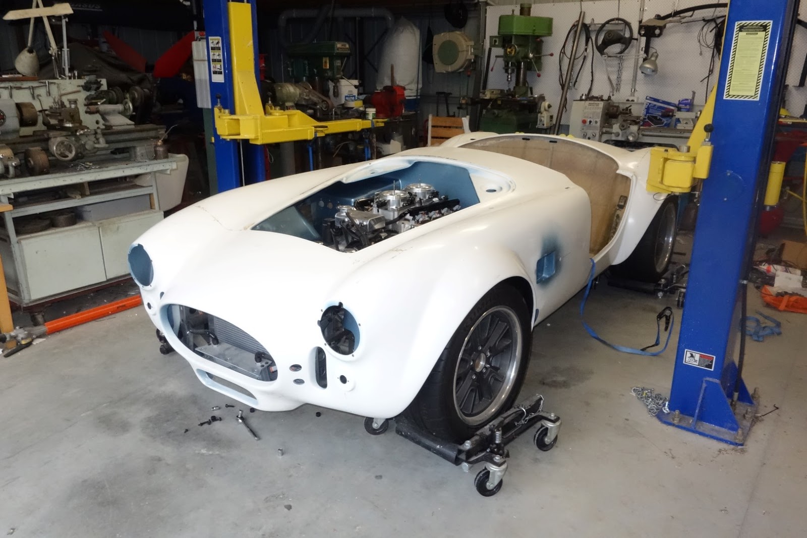
Up on the hoist for a panoramic pic and a look to see if any wiring or other items pinched between the body and chassis.
All looks good.

Spent a fair time tweaking the body on the chassis to get it as square and levelled as possible before installing mounting bolts.

Installed the bonnet mounting brace loosely,
Its the black bracket in the background behind the PWM fan controller.
The Fan controller is a corvette part and is pulse width modulated by the ECU to provide variable fan speed based on engine temperature.

Put the bonnet on and packed it up to be levelled to the bonnet opening then tightened up the bolts to the hinge so it aligned with the mounting brace.
then positioned the brace to align with the hinge pivot tube.
Tightened up the brace bolts that sandwiches the body and chassis with the brace.
Attached the bonnet struts and removed the packing.
Next step is to make some hinge pins with removable clips for easy removal of the bonnet when required.
It wasn't without emotional pain or damage unfortunately, half way through lowering it, I had to remove the oil cooler to get the lower oil cooler body opening over the front outrigger bar.
In the process of lowering the body, I forgot to remove a wiring loom earth bolt on the chassis out rigger that secures the inner front wheel arch, cracking the fibreglass and chipping a bit of paint.
Should be an easy repair at some point down the track, but annoying all the same.
Thankfully, Diane is immune to my expletive rants. Thank you truly.
Ready....
Set....
Used bike tie down straps to hold up the body. These make for easy adjustment of the install angle.
Front has to clear everything then body pushed backwards and held against the outrigger while lowering for the body to clear the engine and quick jack mounts that protrude up through the boot floor..
Go !
Oh No, something went crunch.....
I'll clean this up by putting tape over the back of the wound to secure it, then bonding with resin, reshape, then remove the tape and do on the back side before touching up.
Up on the hoist for a panoramic pic and a look to see if any wiring or other items pinched between the body and chassis.
All looks good.
Spent a fair time tweaking the body on the chassis to get it as square and levelled as possible before installing mounting bolts.
Installed the bonnet mounting brace loosely,
Its the black bracket in the background behind the PWM fan controller.
The Fan controller is a corvette part and is pulse width modulated by the ECU to provide variable fan speed based on engine temperature.
Put the bonnet on and packed it up to be levelled to the bonnet opening then tightened up the bolts to the hinge so it aligned with the mounting brace.
then positioned the brace to align with the hinge pivot tube.
Tightened up the brace bolts that sandwiches the body and chassis with the brace.
Attached the bonnet struts and removed the packing.
Next step is to make some hinge pins with removable clips for easy removal of the bonnet when required.
Subscribe to:
Posts (Atom)