Welcome

Welcome to my Cobra Replica build blog.
Please contact me if you would like to know more detail as i progress."CR3514@live.com.au"
Regards
Dave

Friday, September 30, 2016

Engine Started

A big milestone ,
Started the engine, I was expecting the worst, but it fired right up.

The start wasn't without problems though;
Engine was idling at 1900rpm.
IAC didn't function and seemed to get worse.
Rear block off IAC plug was letting air past.
Air leaks from under the quads.
Huge amount of air being sucked through the PCV circuit.
Thermostat didn't start opening till about 210deg, and the coolant spewed out from under the pressure cap shortly after.

Headed back to work to ponder next actions over the fortnight before returning to tackle the issues.

First up was the leaks under the quads, after removing the first quad, i realized that the IAC port machined into the base of the throttle body over hung the inlet manifold.
After looking up the Holley web site, I found they have a plate that installs below the Quad specifically for this purpose, but also that it was supposed to be supplied with the throttle body, a quick search through the packaging revealed them tucked away in a paper envelope the same size as the base of the box, though i didn't realize it at the time.


In this pic, you can see the port overhanging the plate I made to mount the the throttle cable to.

The plate I made to suit the manifold shape didn't cover the IAC port.


Here is a pic of the Holley plate with the extension to cover the IAC port facing towards the right in this pic.


Next up was the amount of air being sucked through the Oil Catch-can and PCV circuit.
After doing some Googling, I found that the original inlet manifold PCV circuit entered the manifold behind the throttle body, so got my old manifold out for an inspection and found the tube internal diameter is 2.5mm, The hose and fittings from the PCV to the catch-can and then to the quad on my setup is -4AN, (1/4" - or 6.35mm).
This was causing way to much air through the breather port on the rocker cover, so i machined up a restrictor to fit inside one of the port fittings on the catch-can.


This is a -4AN orb fitting, which i drilled out the centre to create a ledge for the restrictor to nest into.
The hose fitting that screws on to the port fitting is slightly smaller hole diameter, so the restrictor is locked into place.


This is the Oil vapor separator (Catch Can).
The PCV circuit is located beneath the valley plate on the LS3, then hose to Catch-Can, through the oil separator and back out again to vacuum port on the forward throttle body.

 The restrictor is in the Oil Catch-Can fitting on the left as it exits to the throttle body. (left most arrow)


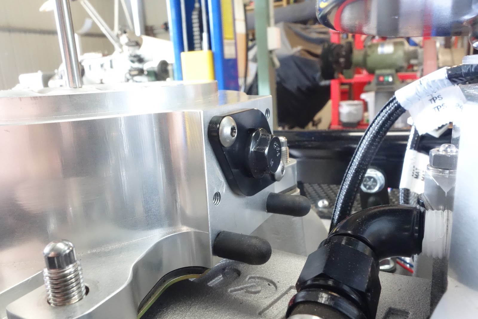
In this pic you can see on the right throttle body the PCV return fitting.


Also on this pic is the modified Rear IAC port block off plate, with a bolt now threaded through it to apply pressure to the plunger  so air cant leak past.


The most thought provoking fix was the coolant leakage under the cap.
After reading many blogs, I found some information on the LS cooling circuits, including the suggested fix for the LS3 style thermostat not opening.
Basically, on the LS3 thermostat, there is no coolant bypass holes in the pressure by pass plate as on the LS1s., and Ls1 thermostats dont fit LS3 pumps.
The LS3s rely on coolant flowing out the heater circuit on the engine side of the pump and back in across the thermostat on its return to the pump.
I had these ports blocked off as i don't have a heater.
The thermostat would eventually open, but at a much higher engine temp.
The other suggestion on Pirate4x4 was that LS Header tanks should be on the "Low Pressure" side of the cooling system due to higher pressure in the circuit and pump flow pushing the pressure cap of its seat.
My header tank was plumbed straight off the pump outlet.
A Good Read.
http://www.pirate4x4.com/tech/billavista/Cooling/#LSCoolingSystems

So some plumbing changes now have the Header Tank plumbed in to the Heater return port with Radiator bleed and Head Steam Vent tubes providing continual circuit of water over the thermostat.

All coolant problems now solved with the revised plumbing and thermostat opening at correct temp and timing.


Last problem was the IAC.
I tested it as per Holley EFI forum suggestions, by changing the "Parked" settings on the ECU to 0% and then 100%, the IAC didn't budge from about 50% open, and when the engine was running, the IAC would read as closed, but would hover around the 20+% open.


I was thinking Holley IAC, Holley Wiring Loom, Holley Dominator EFI, should work together until it dawned on me I had an LS2 spec loom and so it would be to suit a GM type IAC.
This was confirmed when I found that the Holley IAC is a Chrysler type. A check on the wiring diagrams confirmed the difference between the LS2 and Generic Holley looms.
Same Connector, Delphi 150.2 4 pin, but the pin assignments are different for the stepper motors.

A simple change of pin locations on the Holley Dominator P1B connector on the loom and the IAC was working perfectly.


I changed the pin positions on the ECU end as the pins remove very easily by pushing a locking tab and then pulling on the wire.

The Delphi 150.2 plugs however are a pull through wire type connector and  i would have had to get new terminals and rewire.


I also finished my aluminium version of the inlet tray,
Mark Nugent from www.marknugent.com.au made it using the fiberglass part I made awhile back as a buck.
I thought the fiberglass part looked a bit heavy but I was happy with the shape and overall look.
Marks work is simply amazing, checkout his Web page, Facebook page and Youtube.


 Set the part up on the router and cut the location mounting holes.


So..... here it is, some video of the engine running.


Wednesday, March 30, 2016

Bits and Pieces

Slow progress over recent times, with work and waiting on bits and pieces or modifying to make them work.

First up was an IAC (Idle Air Control) block off plate so I can remove the unit from the second throttle body.
The IAC is a stepper motor and adjusts to the ECU commands to maintain idle requirements by pulling a plunger out of the throttle plate bypass channel letting more air in, or closing up to limit the air through.
I only need one IAC to operate Idle control, but leaving the second one in place unconnected means the IAC will not block the second bypass with enough force to ensure no leak past.

Programming the ECU to operate 2 IACs was beyond me if at all possible.


The IAC mounted on to throttle body.


In this pic, you can see the throttle plate bypass port with the hole that the IAC plunge blocks or opens as the ECU controls required idle air volume.


The IAC stepper motor.
You can see the plunger end that fits in to the hole in the port.


In this pic, you can see the tapered hole the plunger seats in.


I bought an IAC block off plate from Accufab to replace the motor and block the hole but it didn't fit.
The seal boss didn't fit in the port, The mounting holes don't line up on the face, and the hole plug was 3mm short of blocking the bypass hole.

I'm not sure if there are other IAC versions so close in design, but the Holley IAC is identical in measurements to the LS1 unit from GM, that I assume its a standard part, so maybe the block off plate was machined wrong, either way it didn't fit.

After pondering and considering the part a waste of time and money, I decided to machine it up to fit utilizing the IAC plunger and compression spring and the Accufab block off plate combined.


So, here is the new improved version.

Machined the 'o' ring boss down so it would slide in to the TB recess.

Then I discovered the mounting base wasnt square to the shaft, so faced the inside of the mount.


Then shortened the shaft and drilled and machined a hole for the spring and plunger to be inserted.


In this pic you can see the misaligned mounting holes.

so, rotated, drilled and tapped 2 new holes.

Job done, hope it works.


The ECU I'm going to use is the Holley Dominator EFI, in conjunction with Holley's harnesses.
The engine harness is for an LS2 as its the nearest fit in terms of sensors and connections excluding the MAP sensor. Easily fixed with an LS2 to LS3 map sensor adapter pigtail.
It also has standard GM Air Inlet Temp (AIT or Manifold Air Temp) sensor plug.
But there is no Alternator circuit in the loom.
The alternator is a Mitsubishi 2 wire 140 Amp (Standard on AU version LS3's and probably some others as well).
The plug terminals are L and F which I understand to be "Line" and "Field"
The F terminal is for the original ECU and BCM to monitor alternator output (via PWM signal) and compare with battery condition.
The ECU then pushes a PWM signal back via the L terminal to set the required Alternator output voltage.

With the plug disconnected, the alternator will default to 13.8v output.
The Dominator is programmable to output PWM through simple configuration tables.

The problem was finding the plug to suit, however I eventually found the part number and eBay to the rescue so here is the details for others.


ACDelco PT2787


Mitsubishi 140 AMP Alternator


The body is off again and upside down for cleaning up and painting the underside.


TPS (Throttle Position Sensor) and IAT (Inlet Air Temp Sensors fitted and wired.

Holley Loom is plug and play.


Crank Censor, Knock Sensors, Coils, Cam sensor all wired.


Waiting on a pig tail for the LS3 EVAP Purge solonoid.
LS3 Evap Purge Solenoid Plug
Part Number is Dorman 645-631
Another elusive plug.


Thursday, January 7, 2016

Windscreen, Roll Bar, and Dash Progress

Fitted up the Windscreen, some careful measuring and confirmation from other CR builders and it was time to cut the body.


The windscreen is from Brasscraft in the UK.
Beautiful piece of work.


I left the plastic sheet on for time being to protect from dust, bird poop etc,
This aided in the fitment of seating the windscreen down on the body as the rubber seal slid on the plastic instead of gripping on the body.


After marking the hole, I drilled a hole at either end and cut between them with an air powered mini saw.

I have used the mini air powered saw for all the body cutouts so far. not much dust created, easy to control with a fine tooth blade, no chipping and no exposed fibers on the finished cuts.
Then I use a sanding bit like a die grinder bit in the Dremel to do any finishing.


Under the dash,
The windscreen legs need to be drilled and spacers made to fill between the Dash Hoop mounting and the legs.


Started on the roll bar, but not fully welded up yet.

The hoop was rolled by another CR owner Mike Murphy, ("Aussie Mike" on the Clubcobra forums.)
Mike's attention to detail and finish is excellent.

The hoop is near perfectly formed using his mandrel bender.


I actually pre-built the roll bar on the chassis before putting the body on,
Once aligned and tack welded, it was then an easier process to mark the hole location and angle after body installed.
I did this the same way as the lift jacks by making a bung for the upper tube and marking and drilling a pilot hole, then from underneath i put a hole saw pilot drill through the hole and used the bung in the upper tube as a guide.


This is not the 3rd leg mounting location specified by Classic Revival, but relocated forward.
Other CR builders discovered an interference with the boot lid mount hoop bar which they had to then modify.

The 3rd lag has a roll bar connection in it to make removal and fitment easier.


Fitted up the dash and after some careful measuring, put a hole in it for the steering column.

The dash panel is normally fiberglass which has a recess pre molded in to it to clear the steering column shroud as standard on the Suzuki Swift/Barina, but i am not fitting this shroud or stalk assemblies, so Daniel at Classic Revival made me an Aluminium panel.


Some minor trimming to the top edge of the dash to follow the curvature of the body and bolted it in.


I've made the hole an oval so I can pass horn, indicators, wiper, and cruise control wires through underneath the column.


Momo Trek R Steering Wheel and Momo Column Boss Adapter 8907 for Suzuki Swift.