First up was an IAC (Idle Air Control) block off plate so I can remove the unit from the second throttle body.
The IAC is a stepper motor and adjusts to the ECU commands to maintain idle requirements by pulling a plunger out of the throttle plate bypass channel letting more air in, or closing up to limit the air through.
I only need one IAC to operate Idle control, but leaving the second one in place unconnected means the IAC will not block the second bypass with enough force to ensure no leak past.
Programming the ECU to operate 2 IACs was beyond me if at all possible.

The IAC mounted on to throttle body.

In this pic, you can see the throttle plate bypass port with the hole that the IAC plunge blocks or opens as the ECU controls required idle air volume.

The IAC stepper motor.
You can see the plunger end that fits in to the hole in the port.

In this pic, you can see the tapered hole the plunger seats in.
I bought an IAC block off plate from Accufab to replace the motor and block the hole but it didn't fit.
The seal boss didn't fit in the port, The mounting holes don't line up on the face, and the hole plug was 3mm short of blocking the bypass hole.
I'm not sure if there are other IAC versions so close in design, but the Holley IAC is identical in measurements to the LS1 unit from GM, that I assume its a standard part, so maybe the block off plate was machined wrong, either way it didn't fit.
After pondering and considering the part a waste of time and money, I decided to machine it up to fit utilizing the IAC plunger and compression spring and the Accufab block off plate combined.

So, here is the new improved version.
Machined the 'o' ring boss down so it would slide in to the TB recess.
Then I discovered the mounting base wasnt square to the shaft, so faced the inside of the mount.
Then shortened the shaft and drilled and machined a hole for the spring and plunger to be inserted.
In this pic you can see the misaligned mounting holes.
so, rotated, drilled and tapped 2 new holes.
Job done, hope it works.
The ECU I'm going to use is the Holley Dominator EFI, in conjunction with Holley's harnesses.
The engine harness is for an LS2 as its the nearest fit in terms of sensors and connections excluding the MAP sensor. Easily fixed with an LS2 to LS3 map sensor adapter pigtail.
It also has standard GM Air Inlet Temp (AIT or Manifold Air Temp) sensor plug.
But there is no Alternator circuit in the loom.
The alternator is a Mitsubishi 2 wire 140 Amp (Standard on AU version LS3's and probably some others as well).
The plug terminals are L and F which I understand to be "Line" and "Field"
The F terminal is for the original ECU and BCM to monitor alternator output (via PWM signal) and compare with battery condition.
The ECU then pushes a PWM signal back via the L terminal to set the required Alternator output voltage.
With the plug disconnected, the alternator will default to 13.8v output.
The Dominator is programmable to output PWM through simple configuration tables.
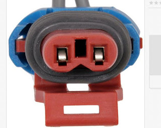
The problem was finding the plug to suit, however I eventually found the part number and eBay to the rescue so here is the details for others.

ACDelco PT2787
Mitsubishi 140 AMP Alternator

The body is off again and upside down for cleaning up and painting the underside.

TPS (Throttle Position Sensor) and IAT (Inlet Air Temp Sensors fitted and wired.
Holley Loom is plug and play.

Crank Censor, Knock Sensors, Coils, Cam sensor all wired.


Waiting on a pig tail for the LS3 EVAP Purge solonoid.
LS3 Evap Purge Solenoid Plug
Part Number is Dorman 645-631
Another elusive plug.

