Welcome

Welcome to my Cobra Replica build blog.
Please contact me if you would like to know more detail as i progress."CR3514@live.com.au"
Regards
Dave

Tuesday, March 13, 2012

Drive Shafts

The CR uses custom axles produced for Classic Revival.


The custom CR shaft on the left is about 67mm shorter than the original VE HSV GTS shaft on the right.

Ian at Classic Revival carries 2 different spline versions pending which CV type you end up with.

Holden changed shaft spline diameter at some stage.


Comparison, the Black painted Inboard CV is from the VE HSV GTS Cradle Assembly I bought from Dubbo Wreckers.

The Green CV is from a VE SS 6.0L V8


No optical illusions, both sitting on the desk, this is the inner CV cage, VE SS V8 on the top,       VE HSV GTS on the bottom.


To fit the massive GTS CV's the diff had to drop a few mm's by removing the Rear Mounting Bolt
to clear the upper control arm mounting.

Once installed, plenty of clearance allround through suspension movement.
No need to drop diff with standard VE CV's


Clearance on installation is just slightly too tight with the GTS CV's


 CV Boot bands not fitted yet.

Saturday, January 14, 2012

Steering Rack Tie Rods

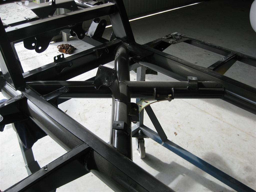
The CR chassis has been jigged up to accept the VP commodore steering rack.
I purchased a reconditioned Power Steering Rack which came with new Tie Rods, but no Tie Rod end ball joints. A quick email to and fro with Classic Revival advised that VP Tie Rod Ends should be fitted.

The Steering Rack fitment to the chassis is accurate, no mods neccessary.

When test fitting the rack however, I found that the VP Tie Rod Ends didnt fit the VZ Knuckles properly.
The issue is the Rack End Ball Joint stud is too big in diameter to fit the small VZ Knuckle taper and seats only partially through the Knuckle Steering Arm.


Steering Rack as delivered, no Tie Rod Ends fitted.


VP Tie Rod End doesnt fit far enough into the VZ Knuckle Steering Arm.


The taper is the correct degree, but too large in diameter.


The next step was to go and purchase VZ Tie Rod Ends, These fitted the VZ Knuckle perfectly, but didnt screw on to the Tie Rods.
The VP Tie Rod Ends are 14mmx2mm pitch  thread, the VZ is 16mmx2mm.
At this point I reverted to the ball joint and tie rod end bible, The Roadsafe Suspension Catalogue, can be found online at:
http://www.roadsafe.com.au/downloads/CatalogueEdition6-4-041011.pdf

I could not find a Tie Rod End with 14x2mm female thread and small diameter 10degree stud, so after comparing VZ and VP Tie Rods at the local parts store, I purchased VZ Tie Rods to retro fit to the VP rack, the inner joint is identical, but the rod needs shortening by 20mm, an easy task.


Remove the lock nut from the Tie Rod.
Cut the boot zip ties and remove the boot from the rack.


Bend back the locking tab, a new tab is supplied with the New Tie Rod.
Un-screw the ball joint housing from the Steering Rack End.
There are flats on the Ball Joint Housing for a spanner.


Tie Rod removed.


The original VP Tie Rod length is 305mm
The original VZ Tie Rod length is 325mm
Shorten the VZ Tie Rod by 20mm, I used an angle grinder with thin cut off blade, then chamfered the end with file.
Extend the thread length by 20mm with 16mmx2mm Die Nut so the VZ Tie Rod Ends can screw on far enough with adjustment room for Toe in and Lock Nut.

The extended thread will run over the top of the machined adjustment flats on the Tie Rod.

Screw the Tie Rod back on to the Rack End, use some some Anti Seize on threads.

Fold over the locking tab.

Slide on the Boot Cover, fix with new Zip Ties.

Refit Lock Nut and Tie Rod End.


Finished, .....almost.


I didnt like the thread sticking out past the Lock Nut, so I've machined up some tapered covers and brazed them to the nut to smoothen the look.

To adjust the toe in/out, i undo the lock nut revealing the flats on the Tie Rod Shaft, adjust by turning the Tie Rod Shaft, then re-tighten the Lock Nut.

Sunday, November 20, 2011

Diff Flange

(Mods - Please read future post "Tail Shaft Part 1" for details where i changed the handbrake cable bracket location and reverted back to OE flange)

The diff flange that comes on the VE Diff has to be changed as it is too big and hits the handbrake cable mount in rotation.

The CR manual details the fitment of Ford BA Diff Flange part number (BA4851A).
The part was impossible to locate second hand without buying a complete M86 Ford Diff, so a new one was purchased, parts are limited in availability as the part is no longer manufactured.

The Ford part however didnt fit without modification, the dust cover isnt pressed on far enough for the shaft to seat on the Diff Pinion Bearing, and the shaft diameter is smaller than the VE part meaning it doesn't seal against the Pinion Seal. The VE shaft is 55mm, the BA part is 54mm.

After scouring the web, found a suitable oil seal, SKF21283, 54x80x10 which will do the job perfectly.


The standard VE Commodore Diff Flange is too big, it hits the handbrake cable mount during rotation.
The Ford BA Diff Fange Part BA4851A specified needs the Dust Cover to be pressed on further to clear the Diff Seal Housing.
In this photo, the dust cover has been pressed off and the dust cover stepped area above the diff seal shaft area has been lengthened by 3mm.


The Diff Pinion Seal needs replacing with smaller shaft ID of 54mm to suit the Ford diff flange shaft.

The original seal is easy to remove by inserting a flat blade screw driver behind the lip seal and levering outward.


Universal Seal Part Number is 21283, made by either SKF, CR, Timken etc.
54x80x10 Single Lip Oil Seal


Done.

Shocks

Received my shocks in dribs and drabs over the last few weeks, Purchased from Summit Racing, they neglected to write "New" in a customs declaration which meant the items were quarantined for several weeks, (8), This was a highly anxious time as nobody knew what had happened to them.
Neither Summit or iParcel could track the parcel beyond it arriving in Australia, customs denied it had been submitted to them and even though Auspost had sent me a parcel tracking email for both packages, only the manifest had been presented, the parcels had gone missing.
I was going down the track of replacement discussions with Summit when iParcel manage to find the rear shocks in quarantine, had been sitting there for weeks without action, Discussions with AQIS finally allowed the parcel release, and a day later delivered, fronts turned up during this week having suffered the same fate.

The shocks are QA1 Double Adjustable with spherical ball ends, DD403 for the fronts fitted with 10" 375 pound QA1 springs and DD501 for the rears, fitted with 12" 400 pound QA1 springs, both with bearing seats for adjustment ease.
(Mods - After fitting sway-bar, future post, I realized I had fitted the shock lower front mount in the wrong spot, too far forward, the suggested 10" front springs meant the adjusters on this shock type interfered with the lower arm unless the spring was compressed 20mm, the result was new front 9" springs, now there is plenty of clearance through the whole movement).

They look great, very nicely finished.

Made up some bushes to space them in the chassis, shocks had to be off set in the mounting for clearance.


Front RH Shock mounted.


 Equally spaced at the top


Compression and Rebound Adjusters.


Offset spaced at the bottom so that spring adjuster clears the Lower Suspension Arm at full droop.


Rear RH Shock mounted.


Offset spacers 4mm to rear so spherical bearing mount clears chassis mount.


12" Springs compressed 15mm to clear Lower Control Arm at full droop, 11.25" length Springs would be ideal


Offset spacers so Shock Body clears Lower Control Arm.


Rear Shock Adjusters easily accessable through factory slot in Lower Control Arm.
Adjuster Knobs also have slots in them for screw driver adjustment.

Sunday, November 13, 2011

Suspension Arms & Diff Mounting

Wednesday, 23rd August 2011
Front Suspension Arms mounted with VZ Commodore modified knuckles, All the Arm joints have been filled with fibre reinforced filler, then sanded primed and 2 pak coated in gloss black.
The Knuckles are ceramic coated in Aluminium by HPC Performance Coatings.
All the fixings, bolts and nuts , have been ceramic coated in gloss black, the coating is far more durable than paint or powder coat.

Front Suspension Arms.
Custom CR upper and Lower Arms, VZ Knuckles.
Rear suspension Arms,
VE Commodore Rear Lower Control Arm, Front Lower Control Arm, Tie Rod, and Custom CR Upper Control Arm.
Original and new factory bolts and nuts, cleaned and HPC coated for a durable finish.


VE Diff mounted, 3.7:1 LSD


The original diff flange hits the handbrake cable mount, some discussion with club cobra members determined i had missed a step.
The manual details the fitting of a Ford BA flange.
Need to scour the wreckers.

Saturday, November 12, 2011

Chassis & Suspension Painted

Wednesday, 21st September 2011
After inspection of the painted chassis, I found the eurothane paint was peeling off the chassis around the rear suspension mountings, also wasnt happy with the welding "neatness", there was a lot of spatter on the frame, i started off sanding the paint back for a recote, but the paint just flaked off, the chassis was supposed to have been sand blasted before coating, but it wasn't, and the round uncoated tubing felt greasey in many places.
I had originally wanted a silver chassis, but this couldn't be accomadated with CR, as they only used eurothane paint and solid colors are all thats available.
I had concluded that black was the way it would be, but having to repaint gave me the desire to change color again.
Chassis went off for sandblasting, then cleaned off the spatter and etch primed.
I decided to smooth the welds, most have been filled by finger with fibre reinforced putty, the underneath (visible areas) have been wiped with a radiused spatula to create a nice smooth looking rounded joint, sanded several times  with spray putty in between, about 100 hours spent on this activity.
I wanted a warm silver, like slightly burnt chrome, I had always liked the Lamborgini colour Titanium, a PPG paint
The chassis was painted black again first, with De-Beers 2 pak, then De-beers Titanium in PPG color code 210600 then some coats of clear with 50% matting agent to give a satin finish.


Chassis before sanding back and top coating.


Chassis painted in PPG color Titanium Silver 210600.
Painted with De-Beers 2 Pak Paint.


Front Cross Member


Left Hand Front Suspension Mount.


View from the rear.

Temporary Separation

Thursday, 16th June 2011
Separated the body from the chassis, easily done, remove chassis bolts, doors, door mounting frame, lift from the back shift forward about 50mm, then lift.
I used Fergie again, made it easy for Di and I to manuvere the body and role the chassis out from underneath.


Body sitting on a pallet, now rests up the hoist so i can get the tractor in the shed.

Diff Finished, nearly

Saturday, 11th June 2011
After trying all sorts of cleaners and acids to refurb the alloy look of the casing, ( phosphoric acid did the best job, but sandblasting would have been better)  I decided on a different scheme, a Monochrome look of Black and Silver, so the drive line is now going to be Black.

Cleaned up the casting marks and painted Metalic Charcoal, too light, so then Metalic Black, The gloss level wasnt enough and the paint (Enamal) chipped to easily, so i bought a new spray gun and tried my hand at 2 pak. Its now just Gloss Black.


Metalic Charcoal, prior to Metalic Black, Prior to plain ol' Gloss Black

Parts Stripped and Ready for Paint

Monday, 30th May 2011
Stripped the VE Rear Cradle, cleaned all the parts ready for paint.
Rear knuckles were very difficult to disassemble, even with correct tools,
Particularly the removal of the backing plate requires the removal of the wheel flange,
The main bearing is a once only use, removing the flanges destroys the bearing inner. *noted in VE/G8 workshop manual. The assembly is so awkward in shape, its difficult to mount in press, so we remounted in the cradle and pressed out from the inside with a car jack.
Also the bushes were difficult to remove, needing some simple custom made pullers to remove, lathed up from some tubes to fit over the bush, then rods and nuts to pull the bush into the tube.

Naked Knuckles


Suspension Arms, Un-modified Front Knuckles on right

Tuesday, November 8, 2011

VE Commodore Rear Cradle

Thursday, 7th April 2011
The CR uses many VE Commodore rear suspension parts,
Lower Arms, Trailing Links, Tie Rod Arms, CV's, Knuckles, Diff.
My Rear cradle came from a 9000K HSV GTS rollover with 3.7:1 Ratio LSD Diff.
I wont be using the standard rear brakes, instead, AP Racing Calipers on DBA rotors.
Cradle as delivered
Fergie does all the hard work again


On the bench ready to be Stripped, Cleaned and Painted.