Welcome

Welcome to my Cobra Replica build blog.
Please contact me if you would like to know more detail as i progress."CR3514@live.com.au"
Regards
Dave

Friday, October 2, 2015

Body On

After putting some rubber insulation tape on the chassis to soak up any vibrations with the body, we lowered the body on with the use of some tie downs (adjustable for getting the right angle) and the car hoist.
Had to remove the oil cooler in the process to get the body in the right spot to clear everything.


3mm Rubber adhesive tape attached to the frame where the body touches.

Along the sides, around the trunk, and the frame area over the rear suspension.


Also had to remove headers, and shift lever to fit the body down on to the chassis.


The wheel jacks, (great fathers day present :)) make it so easy to move the chassis around within the confines of my shed.


Sitting on the ground.
Initially, the rear of the car was sitting 50 mm too high at the lowest suspension settings.
The springs were the suggested 12" specification,
I had 10" springs spare from when I found the front springs were too long, so in this pic you can see the car at correct ride height with the 10" springs fitted in the rear.


The result of this is that when the car is lifted and the suspension fully extends, the spring drops off the top locator by about 25 mm

There is 2 solutions to this;
Get a 2" shorter shock (17" to 15")  with a 1" shorter spring (9") which is same as the front setup.

I know this works because I pulled off one of the fronts and put it in the back.....perfect.

or the much cheaper option of installing helper springs.


Helper springs have very little spring rate, and come in a variety of lengths.
The springs and seats I have ordered are about 4lbs rate and 2" long.
These fit between the spring and the spring perch and take up the gap when the suspension is fully extended, but compress up when any load is applied.

I'll post some pics when I fit them.


Fitted up the front and rear indicators and marked up the headlight centers.
The Indicators are an Amber LED unit.

The air filters clear the bonnet opening, but I want to fit my inlet tray under them when I finish it which will raise the filters another 16 mm and I suspect the rear will hit the bonnet, so a little fiberglass adjustment will be needed.


Rear tail lights fitted.
I'm using LEDs for the tail lights, the upper is an Amber indicator and White reversing LED all in one combined unit.

The lower is a Red Brake, Red Tail light LED combination all in the one unit.
I may have to change the lens to the original red to meet ADR requirements as I don't think the "E" marked clear lens has the correct marks required for brake lenses.


Pic of the engine bay,
The left hand header fits with good clearance all round.

The drivers side header just touches the steering column outlet on the body.
I need to decide if I ding the number 8 cylinder pipe in a few millimeters to get clearance, cut it and reshape it, or take a bit off the body.
See what I can live with.


Clearance around the header was a good educated guess seeing as I built them with the body off.


After I cut all the holes for Lights, Side Pipes, Roll Bar, Quick Jack mounts, Side Lights, Steering Column, etc,  I'll remove the body again for cleanup and painting underneath before final fitting.

Friday, September 11, 2015

Some Underneath Shots While On The Hoist


Classic Revival's' chassis has close similarities to the original Cobras'.


Seldom seen, the VE commodore lower control arms, diff and the drop tank.


Under the hood.


LH Rear


Caliper CP5147 RH Rear


Handbrake cable end in VE Commodore rear knuckle.


Front
Valves are 45deg bend to clear the calipers.


Thursday, September 3, 2015

Tyres Fitted and Balanced

Finally at the Go-Kart stage.
Got the tyres fitted, balanced and dropped the chassis for the first time in 4 and a half years.


Tyres are Kumho Ecsta XS KU36

245/45ZR17 on the front.


285/40ZR17 on the rear


A quick string line alignment for front and rear toe in, and camber adjustment with a cheapy camber bubble gauge.

Sunday, July 26, 2015

Inlet Tray - Part 1.

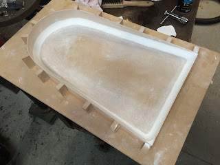
I've started  building the mold for the Inlet Tray
The idea is a tray that is shaped around the Hellings and Stellings air cleaners and follows the taper of the hood under the inlet scoop.
Minimize the hot under bonnet air going into the inlet.

At this stage I'm thinking of having a slim tray on top of the quads and a foam rubber seal stuck to hood that will seal up against the tray when the hood is closed.


This is the concept I did awhile back in Sketchup.


3D model of the tray in Sketchup


The next step was to unfold the 3d model and flatten so I could create a line drawing of the parts to import into Vectric Cut2d program and export tooling parts to my cnc router.


After flattening, I delete the surface and export the lines as a .dxf file then import into Cut3d to create the tool paths in G-Code.


Here is a pic of the side wall cut from 3mm MDF board, and a 1/8" groove machined into a 12mm base board which the side walls slot into.


The 3mm MDF bends around the curve easily, slotted into the groove and then glued with PVA glue, very rigid.


Next step was to create a radius around the base to soften the edges.


I cut a 20mm radius in a plastic spatula and spread cornice plaster cement around the base profile and walls.

Cornice cement dries quick and holds it shape while spreading.
Its also very easy to sand and smooth before putting some filler over the top to protect it.

I also glued on some side supports to mount a flange around the top of the mould.


Next step was to cut a flange and glue and screw to the mold.

In this pic i have filled the edges and spray puttied the mold, sanded and started filling the imperfections with some body filler.


I am undecided as to have a go at vacuum forming with 4mm Acrylic sheet into the mold or fiber-glassing a part from it.

More next time.


Tuesday, July 21, 2015

Wheels & Tyres - Part 4

Picked up my wheels.
Looking the goods, and very happy with the finish.
The fronts need to go back for a little off the spigot bore as they are just a little too snug.
Everything rotates as it should, with good clearance.


Friday, July 3, 2015

Wheels & Tyres - Part 3.

Visited Dragway today to confirm measurements before they welded the centers into the rims.
Took some more pics, measured the front space on Front and Rear Assemblies, centres hole and bolt PCD and the Caliper clearance from the hub mount face to the centre webs.
All good to go.


Front Wheel assembled and ready to weld then trued up and hub faced square to the rim.


Inside view of the Front Wheel.
In this pic, you can see the tape protecting the edge of the center from paint overspray before welding to the Rim.


Rear Wheel assembly.


Centers painted and awaiting assembly.


Center Caps all machined and painted.


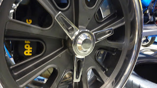
This is a spinner that has been machined from a billet into the section profile before having the spinner shape machined.


Underside of a spinner, still to be center drilled and tapped for assembly to a boss that clamps through the Center Cap.


Spinner sitting on a Center Cap.

Wednesday, July 1, 2015

Wheels & Tyres - Part 2.

Some more wheel progress pics arrived today.


Monday, June 29, 2015

Wheels & Tyres - Part 1.

Wheel spec for the CR is a difficult choice if you want to go the traditional look with the Halibrand style and Knock Off Spinners.
The track of the hub faces is very wide both front and rear and so a small Front Space (Distance from rim outer edge to the wheel mounting face) is required for the wheels to fit under the guards.

All the usual after market wheel manufactures cant get to this offset without the centres sticking out past the JJ rim profile inner step, and the spinners stick out past the wheel & tyre which is illegal.


Don't like this look :(


When I bought the chassis and body kit, there was an Australian Manufacturer that did make a custom wheel for this spec, but they had ceased to make them and wouldn't consider to do a run even for a group buy.

The CR spec is 3" Front Space for the Front Wheels and 4.5" on the Rear Wheel.

Both Team 3 and Vintage Wheels in the US were great to deal with, and have great looking wheels, but unfortunately couldn't get the required spec,
Team 3s best effort was still a 1/2" off the front space requirement, mainly due to the cast center profile and my need to clear the calipers which stick out past the mounting face by 7mm.
The design of their cast centre prohibited further machining of the back face to clear the caliper and achieve the required offset.


A chance encounter with Racecraft Industries in Melbourne revealed a customers "Eleanor Mustang" Replica build, and while having a look over the car, I discovered some Halibrand Style rims that had a different profile.


While this was a 20" rim and I want 17", the rim design might give some option for the front space problem.

The fact that they are from a solid billet gave design options not available on other wheel centers.


These Wheels had a neat little cap that covers the 5 wheel studs replicating the Knock Off Spinner Style Wheels I was looking for.

Other brands have covers that do this but the key point of interest was the Rim Profile.

Contacting the owner established the wheels where custom CNC made for him by Dragway Wheels in King Lake Melbourne using billet aluminium for the centres and welded into a "Smooth Look" Rim from Specialty Rim Supply (SRS) in the US.


I contacted Dragway and organised a group visit with 3 other CR builders.
We spent several hours with Dragway's designer reviewing the possibilities and touring the facility and left confident we could meet the CR requirements.
Further direct contact as we neared purchase time developed a solution that maximized the visible rim and met the caliper clearance, front space requirements.
The aesthetics and legal requirements would be met with a redesigned flatter profiled billet spinner all within the rim.

First to order was Ben, you can catch Ben's build blog here. - Ben's CR Cobra Build

Here is the start of my wheel progress to date.
I finally decided on 17"x 8" rims for the front, and 17" x 10" rims for the rear.

Margie (Owner of Dragway) kindly sent me some progress pics this week of the wheel center machining so far.


Aluminium billet centre.


Rear of the centres have been profiled.
The left billet is a front wheel center with 9mm boss to clear the calipers, the middle billet is a rear with 27mm boss.


Machining a centre with the Halibrand style look.


The tyres I have purchased are Kumho Ecsta XS.
245/45ZR17 for the front and 285/40ZR17 for the rear.


More pics to follow.