Welcome

Welcome to my Cobra Replica build blog.
Please contact me if you would like to know more detail as i progress."CR3514@live.com.au"
Regards
Dave

Friday, May 23, 2014

Sensors & Gauges

My gauges from Speedhut arrived a month ago, I am very impressed with the finished quality and construction of the gauges and the completeness of the fittings kits that come with each gauge.
All quality products.
They even sent a "T" shirt with the delivery. :)

I got them to put my "Classic Revival" logo, and chassis build number on the Speedo.
This can all be done on the website by customizing the gauges to required colours, text, indicators and by uploading images for use as a logo.

Speedhut Gauges
Speedo - 0~260 KPH.
Tacho - Programmable shift and warning lights.
Oil Pressure
Oil Temp
Water Temp
Volts
Fuel Level


Oil Pressure Sender
The switches / senders supplied have 1/8 npt threads, but the LS has metric ports,
The adapter in this pic is from Aeroflow, its a 16mm to 1/8" npt adapter.
Part number AF912-M16-02BLK.
It fits to the original Oil Pressure Sender port on the back of the valley cover.
Water Temp Sender
The adapter in this pic is from Aeroflow, its a 12mm to 1/8" npt adapter.
Part number AF912-M12-02BLK.
It fits to the original Water Temp Sender port on the LH front or RH rear of the heads.
Sacrificial Anode
The radiator is all aluminium and is subject to electrolysis if bad earthing occurs, The LS3 is earthed from the back of the passenger side head on VE Commodores.

I will earth the radiator as well, but as extra protection, i have fitted this Sacrificial Anode, Zinc coated, it screws into the brass 1/4" npt port on the radiator.


Oil Temp Sender
The oil temp sender is mounted in to the outlet side of the oil cooler adapter on the sump.
The sender needs to be shortened to fit into the 1/8" npt port.
The sender is pre prepared for both long and short versions from Speedhut with a cut off groove already machined into the sender probe.

Sunday, April 13, 2014

MAP Sensor Mount

Changing manifolds from the stock LS3 to the Holley Dual Quad Manifold has left me with out a MAP Sensor mount.
The Holley Manifold has a 3/8" NPT port on the back of the manifold as a vacuum port.
Usually this would be used for a Brake Booster or Vacuum Tank, but i will use this port for the MAP Sensor.


The boss on the back of the manifold is shaped like a shield, the 3/8" NPT hole is not central to the boss.


My son Tom is studying year 12 systems engineering, he's in to all the latest tech gear, 2 years ago, he invested in a "Kickstarter" project by a company called Formlabs who were developing a high resolution SLA 3D printer.
For his backing, he was entitled to a 3D printer when they started producing, which we received in March 2014.


Formlabs 3D Printer


So, for the MAP Sensor mount, I designed a part to fit the boss which would be held in place by a 3/8" NPT plug with a 12mm hole bored through it for the MAP sensor to locate in.
The MAP sensor is then bolted to the mount using a Rivnut held in place on the reverse side of the mount.


Printed part using clear resin.

Finished part with a Rivnut insert from the rear with MAP mounting bolt.


Printed mount fitted to the boss.


MAP Sensor mount held in place with 3/8" NPT plug with 12mm hole bored through the plug.


MAP Sensor mounted to the bracket.


Side view,
The mount is recessed to fit over the shield shaped boss.

Dual Throttle Linkage

Made up a Dual Quad Throttle Linkage to connect the the two Throttle Bodies together.

The linkage is made up of  two 1/4" Unbrako Shoulder Bolts that fit through the linkage from the inside then through two 1/4" Rose Joints for low friction and secured in place with Nyloc nuts.

The Rose Joints have threaded shafts, 1 Right hand, the other with Left hand thread connected with an aluminium shaft and lock nuts.
The opposing threads make it easy to adjust the linkage to the correct length by just turning the shaft.

Saturday, March 15, 2014

Throttle Body Studs

Today I mounted the throttle bodies on the manifold with some stainless steel studs to suit the 1 inch throttle body spacer.

I prefer studs for mounting the manifold and throttle bodies.

Need to figure out how to mount the throttle cable.


The studs have dome  ends on them, havent seen these before but the look well finished.
These are ARP brand.

Injector Adaptors

(Mod - See future post for change to LS3 Dual Quad Inlet manifold)

Had a day at home by myself last time i was home, so after it got too hot doing jobs around the place, I spent the afternoon in the shed.

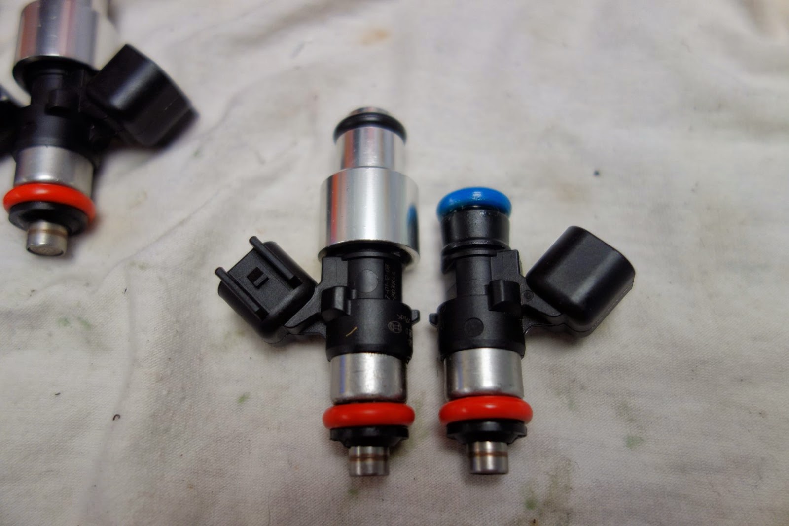
The Holley manifold i've got and the fuel rails are made to suit either a pico injector or the older taller LS1 style injectors, but i want to keep the LS3 ones, so i set about making an adaptor to bridge the gap from injector top to fuel rail, and to lift the fuel rail a little further away from the injector loom connector.
The fuel rails look too tall on the upper mount setting, so i'm going to make adapters that will space the fuel rail about half way and consistent to having LS2 type injectors in case i ever need to change them out.


You can see the gap to bridge between the injector and the rail in this pic.
On the lowest rail setting, the injector is still about 12mm short from seating in the rail.
After a measure up, of the gap, manifold hole and rail holes, i made some adaptors to fit the gap, and added some new Viton O-Rings.


Some aluminium stock in the lathe


This is extender no 2, the 1st adapter was machined from the 'O' ring end and became difficult to machine the injector cavity without damaging the 'O' ring end.
The end mill would spin the finished part in the chuck due to the small clamping area.

In this pic, I've faced the stock, bored and chamfered the injector cavity, drilled the fuel hole, then profiled the adapter.


Next step was to part off and chamfer the adapter end.


Here is the finished part on an injector.
6 more to go.


Mounted on the manifold, 


Pre-assembled, just need to drill and tap the rail posts to lock it all up together.


Thursday, March 6, 2014

Inlet Manifold Adaptor Flange

(Mod - See future post for change to LS3 Dual Quad Inlet manifold)

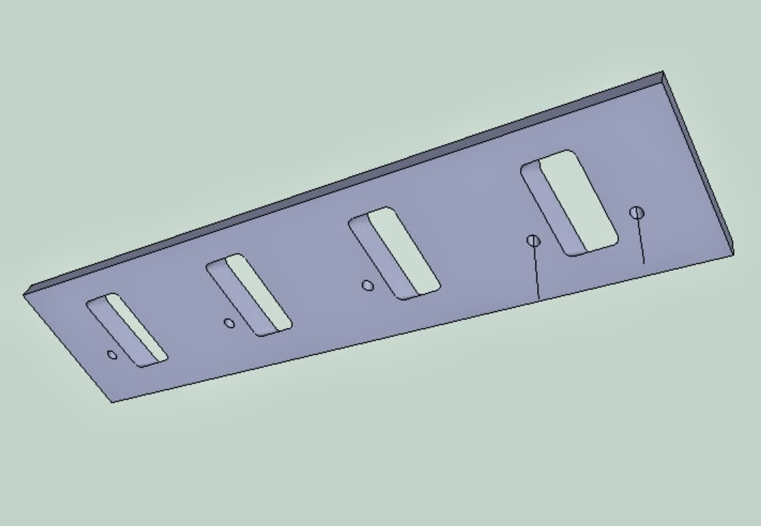
After considering the best way to cut and fill the manifold ports to match the LS3 heads, I've decided not to potentially ruin the inlet manifold and will make up some adapter plates.
10 or 12 mm Aluminium plate is all I will need to smoothly transition the ports without sacrificing cross sectional area.
This will lift the manifold vertically approx 12 to 14 mm depending on flange thickness.

Here's some CAD pics of the concept.

From the Cathedral Port Side (Inlet Manifold)


From the Square Port Side (Head)


Picture showing the port walls morphing between
Cathedral profile and Square Port profile.


The port wall surface data is what I will use to create the machine tool path for the CNC Mill.

The far port wall in this pic you can see is an undercut, meaning i will have to cut a vertical wall on this side in the first pass, then flip the part on my machine to finish this tapered face profile.

Saturday, February 1, 2014

Anniversary Pics

3 year (28/01/2014) Anniversary Pics, another year gone,
Main progress this year was:
Engine and Gearbox installed,
Master Cylinders Installed, and Brake and Fuel Lines completed,
Oil Cooler installed with all Feed and Return Lines,
Evaporative Emission Canister installed,
Battery Installed


Playing with Header Pipe arrangements.


Induction on the go.

Monday, December 23, 2013

Inlet manifold - 3

Home for Christmas this year, and Mr. Postman had turned up with some boxes for me with some goodies to play with over the next few days.

A quick un-box, out to the shed, sit them in place, stare for a while.


Starting from the Top,
Twin Stelling & Helling 8-1/2" Chrome Air Cleaners.


Twin Holley Billet Throttle Bodies,
Part # 112-577,
1000cfm, 44mm bores, with either 1 to 1 or progressive secondary bores.
Comes with IAS and TPS.
Ports for Evap Solenoid and other vacuum or atmospheric devices.


Under the quads sits a 1" bored spacer,
While they purportedly improve torque, i purchased them to bring the height up enough so that the air-cleaners would be visable through the bonnet scoop and the engine would have an overall height in proportion to the original carby heights of about 3 ", the EFI quads are about 2" in height.


Next step is to design the MAP Sensor Mount, and Evap Solenoid Mount, Evap Solonoid Piping to connect up with canister line.
Machine up adapters for the small LS3 EV6 injectors to fit the space normally occupied by the larger LS2 injectors.
Make a Dual Quad Linkage, and a throttle cable mount.
Make a jig to hold the manifold and a port face plate so I can accurately match the ports between the Cathedral Port Inlet Manifold and the LS3 Heads.
(Mod - See future post for change to LS3 Dual Quad Inlet manifold)
Air cleaner plenum tray to fit between the Quads and the Bonnet.
Put Studs in the Heads instead of inlet manifold bolts, and studs in the manifold carb flange in place of bolting the Quads on.

Have a great Christmas all.


Friday, December 13, 2013

Inlet Manifold - 2

(Mod - See future post for change to LS3 Dual Quad Inlet manifold)

So, searching the web for port diagrams displaying relationship to manifold bolt holes or even comparisons of the difference between Rectangle Port and Cathedral Ports on the LS engines doesn't turn up much good info other than photos.

First step in determining if I can port match was to get some accurate measurements from the LS3 heads.


This shows the right bank.
If you look carefully, you can see that the ports aren't parallel to the block face, they are rotated about 2 degrees


Next step was to lay some card over the ports and tape in to space, then using a tack hammer, tap around the edges of ports and manifold locating bolt holes effectively cutting through the card without damaging the head face.

In this pic, you can see where the furthermost front locating hole is punched through the card.


Next step was the manifold purchase.

There is a story that goes along with this purchase that further reinforces my belief that Australian retailers are a rip off and offer lousy service to go along with it.


Nice looking casting until I noticed the manifold is faulty.


Yes, that's where the mill cut through the side of the lower dual plane port into the upper port while machining surfaces,

How this type of defect gets through inspection, I'll never know.


Here's the view from the opposite port.
I understand these things happen, and had the process to replace been quick and efficient then no problems, but the hassle to get it replaced was ridiculous.


This is from a major Australian performance parts supplier, they should change their name from Eagle to Turkey.


Same process with the Manifold Ports.


After profiling the ports, I could overlap the ports to see the variance.

I micrometer the parts and verified on the cut outs then overlapped the measurements in CAD


Here you can see the variance in the overlapped ports when mounting holes aligned.
The blue areas are the Cathedral Port.
The grey groove is the port seal groove in the inlet manifold around the cathedral port.

The Red area is the LS3 rectangle port profile that would need to be machined from the manifold to match.
The dark blue area is where the cathedral port would need to be filled to match the rectangle port.


There appears to be enough material in the manifold flange and port wall thickness to easily achieve the match, but the machining of the port would come right up to the edge of the seal groove.
Some compromising will need to be done if I head down this track, with a few millimeters of clearance to the seal.
Considering the CFM flow of the manifold is rated at 700hp, and my target is 500hp, should have some scope without restricting airflow.

Before


In Progress


More to follow.

Inlet Manifold and Throttle Bodies - Prelude

The more Cobra pics I collect, the more I love the old school look..... Twin Carbs.
But, I love the modern tech and modern materials as well so I'm going with the retro look of  dual quad throttle bodies.

This is one of my favourite Cobra pics, Ken Miles's number 98.
Particularly the shroud surrounding the air cleaner,
It seals up against the underside of the hood.


I also like the twin air cleaner look of the original Stelling & Helling filters with the chrome tops, should look good nestled between some carbon fibre and billet bits.


This is the look I'm going for, modelled in Sketch-up, it gives me some perspective on the overall dimensions and look


There are a few manifold candidates for the LS motors from the big names like Edelbrock, Holley, Wilson, etc etc, in Single and Dual Plane and also some custom manufactured versions, but the high riser singles are too tall and don't have the right look for me.
So, I've settled on the Holley Dual Plane Mid Rise Dual Quad Manifold #300-121,
This was because of the excellent flow rates detailed in several on-line magazine comparisons.


This pic I took off a You-Tube clip when I was trawling for throttle body candidates.
Its the same manifold with twin 1000cfm billet quads, also Holley part #112-577

The fuel rails come with the manifold.


The issues with this set up is that the manifold is made to suit Cathedral Port heads,
My engine is an LS3 with the Rectangular Port Heads.


The 2 options I'm looking at for this is:

option 1. Port match the manifold to suit the heads if possible, initial measurements suggest i can get very close to the same cross section so flow and pressure differences are similar, by widening the Cathedral port and adding some fill to the base of the cathedral port to match heights with the LS3 heads,but,
if there isn't enough material in the side walls of the manifold, then,
option 2 is to fit a pair of Mast 245 heads that have similar port lengths and combustion chambers but with Cathedral ports.

More on my efforts in the next post