Welcome

Welcome to my Cobra Replica build blog.
Please contact me if you would like to know more detail as i progress."CR3514@live.com.au"
Regards
Dave

Saturday, September 14, 2013

Brake Lines

Pretty much finished running the brake and fuel lines,
I started off running 3/16 stainless steel, but changed my mind to steel coated lines, the colour is much nicer and looks better against the chassis. The steel lines are far easier to bend, fit and flare.
I bought a K-Tool flaring tool, and had a few goes at routing the lines till I settled on the final position.
I was also a bit worried about the proposed CR rear brake hose location, probably would have been fine, but the flex hose needs to be deformed a bit and tied away from its natural set position to avoid touching the rim, so I changed the location of the hose end for better clearance.

This is the Front LH Brake Hard Line coming across from the RH Front Brake Line 3 way.

The line exits at the side frame for the suspension arms where it connects to the flexible hose.

In this pic you can see another one of my tube mounts, the lower 1/2" hole is for my Oil Cooler return line.


The Front LH Brake Flexible hose fitted to the chassis side wall.


The Flex Hose has a bow in it to allow enough length to cope with lock to lock steering.


Front LH Caliper banjo connection.
Brake hoses made by BrakeQuip in Pakenham, see Lindsey the owner for good support and quality components.


Rear Brake line travels along the drivers side chassis rail along side my enclosed battery cable.


The chassis clamps are my own design milled from 6061 Aluminium with a 4" radius to suit the chassis.
Tumbled in ceramic to polish and debur before being clear anodized for a Titanium look, then fitted to Rivnuts inserted into the chassis,

The black insulators are fitted to all brake and fuel lines lathed up from plastic rod.

Both tubes sneak between the body floor and chassis rail.


Brake tube travels along the upper rear control arm mount to a 3 way on the rear of the chassis.

The Caliper flex line exits one of the 3 way ports eliminating the provided chassis mount.


The set on the flex hose clears the suspension arms and spring / shock assembly.


Flex hose fitted to the Rear AP Racing Caliper.


3 way fitted on the rear upper control arm mount.
Drilled and tapped a stud into the mount, then fitted 3 way and flanged nut.

The line then continues across the chassis to the LH rear caliper.


Another 3 way fitted on the LH rear control arm mount, 1 port plugged, the other port used for the Caliper Flex Line.


Wednesday, April 24, 2013

Engine & Trans meet Chassis

Its in, or should i say on.
Feel like a milestone has been made when i married up the Chassis with Engine  / Trans,


Front Left Hand Engine Mount Mounted to the Chassis.


Rear mount is standard VE TR6060 gearbox bracket fitted with an off the shelf Mackay Rubber rear gearbox mount part number A1115
Common in many early Holdens.


Rear Mount sits snugly between the chassis cross tubes, there is about 3 or 4 mm clearance to the tubes, may need to be relieved a little more pending how much the engine moves around.


The rear mount sits on the Classic Revival mount supplied with the Chassis.
All the bolt holes aligned perfectly.


View from the LH rear.

TR6060 Tremec 6 speed Gearbox

I spent a lot of time trying different cleaning fluids and chemicals to try and restore the aluminium sheen without resorting to polishing, the box was spick and span, but still didnt look any better so i painted it, and in keeping with my black and silver theme, it ended up black like the diff.
Other than a partial strip to check the condition, the only mods are the remote clutch bleeder and the shifter.

All black, not sure if the original commodore tail shaft flange stays or goes.

This box came with the engine i bought from a 21000k VE HSV,
the insides look like new so back on with the housings and painted up.


After reading that the TR6060 didnt have a speedo drive, i was flicking through a VE assembly manual and discovered that they do have a pulse generator fitted at the rear of the box extension housing on the right hand side.
This has simplified my thoughts of taking the speedo readings from the ABS sensor in the rear wheel.


Reverse Lock Out Solenoid.


The VE Commodore has the shifter mechanism mounted off the rear of the extension housing with a lever shaft and ball mounted back to the center mount.

Removing the cover reveals the ball mount for a mid mount shifter mechanism.


This is a Core - Hurst Shifter mechanism,
All Hurst components fitted into custom TR6060 mid mount housing.

These shifters are less than half the price of locally available options and appear to be very well constructed, the Movement feels very snug but smooth.

Standard Hurst shift lever will bolt straight on.


This pic shows my custom remote bleeder.
The fitting to the slave cylinder is unique, its a custom made 8x1.25mm male thread with convex end on the slave side, and -3AN 3/16 male on the output side, mated to a 3/16 brake flex line.

To make the fitting, i bought a -3AN male to male steel adaptor and machined off the thread on 1 side and then tapped to 8x1.25mm to suit the slave cylinder.

Fitted to the other end of the clutch bleeder line is a 3/16 to 10mm female concave fitting with a Russell speed bleeder nipple screwed in to it.

I still have to make a bracket to mount the end to the gearbox securely so its not floating around.

The Brakequip guy in Pakenham made up the custom length flex brake line with standard fittings..
$55 all up.


Plug Leads

After putting the general engine assembly back together, it was time to plumb some ignition leads to the new coil locations.
I bought an MSD universal engine ignition lead kit which has the plug ends already crimped, but long lengths of lead to be custom cut to length by the installer,
After i routed the leads and marked them up for length, i was surprised to find the kit didn't contain the type of coil connector used by the LS individual coils, i had assumed these would be something common, but not to be.

Plenty of different connectors and caps, including some spares....except the the LS coil type connectors i needed.


The top 2 connectors come in the kit, i found some connectors on the web after feeling like i was being mugged by the local ignition specialists.

The black 90 deg boot came in an LS connector kit from Taylors in the U.S.


After routing the leads, mark up the length of lead to the center of the right angle boot.
I used some zip ties to hold them in place while i adjusted angles and lengths.


I used the crimp length guide and crimp tool included in the MSD ignition kit.
Insert the lead into the tool lining up the mark you made to the left side of the holder, then cut through the silicon lead cover while rotating the lead.
The holder prevents the knife from cutting too deep.


After cutting the silicon sheath and pulling off, fold the lead conductor back under the lead and push into the crimp connector, then insert into the crimp tool, and squeeze together in a vice.


I used the grey 90 deg boots supplied in the MSD kit for a lower profile look over the larger Taylors boots.


The MSD kit also comes with cylinder lead number tags.


Finished.

Saturday, February 2, 2013

January 2013 2nd Anniversary Progress Pic

Where did 2 years go ?


Number plate may be getting a bit ahead of myself, but it was available.

Thursday, January 24, 2013

Engine Assembly - Progress

Over the last few weeks, I've been tinkering with the engine, not performance stuff, just trying to make the engine fit with my black and silver theme.
The LS engines aren't the prettiest out of the box, but they can be made to look pretty good with a tidy up, some color and a bit of bling.


The Progress so far,

Partial strip down, all the accessories off, inlet manifold, valley cover, rocker covers, sump, starter, water pump, timing cover, power steering pump, engine mounts.
This pic is the engine almost back together except for Water Pump, Starter, and Power Steering Pulley.


 In this pic, you can see the LS3 oil pan with rear sump,
The sump on my engine needs to be changed to a front sump due to the placement of a cross member on the chassis.
This cross member placement is a decision you need to make with Classic Revival when you order as it could have been placed further forward to suit later engines than the LS1 front sump version.


Bought a second hand VZ LS1 sump off eBay, stripped it down,
HPC coated in gloss black.
You can see the oil ports available for use after removing the recirculating plate just above the filter mount.


Pulled apart the alternator to clean up and add some color.


The VE alternator is made by Mitsubishi.
The most difficult part of dis-assembly was removing the front pulley, there is no where to lock the spindle from rotating, and Holden doesn't sell spare pulleys, so some care is required.
After trying to shock the nut loose with an impact gun, I lucked on the easiest way to hold the pulley from spinning.
Wrap the serpentine belt around the pulley and clamp belt in the vice, as the vice closes, the belts lock up on the pulley and the impact gun will whip it off easily.
Next undo the four long bolts that hold the 2 halves together.


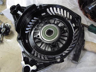
To separate the 2 halves, you don't need to remove the four small screws behind the pulley, these only hold a keeper plate over the back of the bearing.
I removed this and the bearing later so i could get the casting HPC coated.

Wriggling the 2 halves back and forth, the front half will come away from the coils.
you can then easily pull out the shaft and magnet assembly leaving just the coils still screwed in to the back half.


3 screws hold the coil assembly in place, 2 are easily accessible, to get to third, the coils need to be lifted out a few millimeters which bends the wires at the bottom, so care is needed, this will uncover the third screw as can be seen in this pic.
Every thing then lifts out easily.


The trick to re assembling the rotor back into the housing is too press down the brushes in to the bearing housing and insert a pin from the back to hold them down while you insert the rotor shaft back in to its bearing.
You can see the little pin sticking out of the hole in this pic just below the center of the back housing.


Here's a pic with the Alternator, Corvette Engine Mount Bracket, VZ engine mount and sump fitted.


Its funny how the simplest tasks can be quite frustrating,
The pic here is the alternator support bracket.
With the move to the Corvette Engine Mount Bracket, which now mounts to the forward engine mount bosses, effectively moving the engine rear wards in relation to the chassis, the Alternator Bracket sits 12mm off the boss face, and also hit the Engine Mount Bracket forward Web.
Turning it upside down and slotting the mount hole was all that ended up being required.


You may have noticed in an earlier pic the Oil Cooler Adapter, this is from Improved Racing and is specifically designed to fit the LS GTO and Holden LS1 sump and accessories package.
Part number IR-EGM-1007
Its the only adapter i could find that clears the Engine Mounts and Alternator, and doesn't lower the filter below the sump base.

The original LS Oil Gallery Cover is removed to reveal two ports just above the Oil Filter.
The Adapter is a two piece unit.
The first piece is the mounting plate.


This pic shows the port block mounted to the adapter plate.
Two versions are available, -8AN, and -10AN fittings with two 1/8th NPT ports for Pressure and Temp Sensors.


View from below.


View from Side.


In this pic, you can see how the adapter sits in relation to the Alternator and Engine Mount

In the upper right you can see my coil relocation brackets.

The LS3 has the dip stick tube mounting in the block  towards the rear of the engine, as opposed to the LS1 being mounted into the side of the sump towards the front.
In this pic, I've drilled and tapped to suit an M16 grub screw and added some gasket cement around the thread to seal up the hole.


The standard VZ or GTO dip stick tube clears the Engine Mount Brackets perfectly without modification.


In this pic you can see the LH Coil relocation Bracket.
While i hadn't seen this bracket mounted like this before, the holes in the bracket line up perfectly with the bosses in the block previously used by the VE engine mounts.
I'll replace the leads with some right angle versions to clear the exhaust manifolds.


This is the RH Coil Relocation Bracket.
Fits just as neat, but the coil loom plugs interfere with the starter solenoid.

The two choices are either make up a bracket that moves the coils out a bit at the bottom, or get an indexing starter motor like the MSD 5096 model.

These brackets I bought from CBM to suit the LS3 coil.

In this pic, you can see the CAM Sensor extension wire and shield fitted, this is not standard on Holden versions because the loom comes down over the top of the engine.
I saw this part fitted to a crate engine, it suited my needs as i want to hide the wiring as much as practical.
Also in this pic you can see a plug over the crank end i machined up from a bit of acetyl rod i had lying around.
This is to accurately locate the timing cover back into place which needs to seal evenly around the crank balancer and line up with the block sump face to mate to the sump, otherwise they leak.