Welcome

Welcome to my Cobra Replica build blog.
Please contact me if you would like to know more detail as i progress."CR3514@live.com.au"
Regards
Dave

Thursday, August 13, 2020

Brake Cooling Ducts

Decided to create a custom Brake Cooling Duct system for the CR.

Several iterations of this Body Duct - Measure, Design, Print, Fit, re-design etc etc. 

Final design fits to the chassis, fits over the Body inlet duct hole and has an aluminium stand off mounted to the body to aid support. The duct is common to LH or RH Vent.

I printed the parts with Fibre Reinforced Fire Resistant ABS on an Artillery Sidewinder X1 V4 printer.


Finished print before a bit of cleanup.

The outriggers on the sides of the duct are for mounting.


In this pic, from inside the wheel arch shows the RH body duct mounted to the chassis with a crush clamp to protect the duct plastic from crushing, the duct fits over the vent moulded in to the body and is bolted on the RH side to a standoff post mounted to the body.


The wheel side duct went through many iterations of design changes, prints, fitting and adjusting to get the angles and clearance right.

The outrigger is the mounting point to the knuckle.


The wheel side duct is shaped to fit around the knuckle and direct air into the inside of the brake disk, painted in high temp paint and shielded with aluminium insulation foil, it has a 20mm air gap to the disc for  added temperature relief.

The print filament is Fire Resistant ABS. 


The duct is mounted to the knuckle mounting point with a longer M14 class 10 high tensile bolt, the duct fits to the bolt after the knuckle bolt nut is tightened and is secured with a separate lock nut.


Fit up excluding the disc shows the  duct routing.

The duct is 3" dual silicon brake ducting.

The dual silicon  wire wound duct is very heavy and stiff and I will be looking for a lighter less restrictive version. I do like the Red colour though. 😁


Pic from the front .

Monday, December 2, 2019

Battery Compartment Cover

Some more progress on the Battery Compartment Cover.


After priming and filling some rough areas, sanded smooth, primed and coated with acrylic black paint.


Waxed, polished and sprayed with Poly Vinyl Alcohol mold release.

Ready for some mat and resin.
Bought 1m2 of Mat, 1L bottle of  Resin, Small bottle of catalyst, 1L bottle of PVC Mold Release.


2 Layers of 225gsm mat applied with PE resin.
Layers applied about 3 hours apart.

Applied resin with a 1" brush and then rolled with a homemade roller made from 50mm length of 10mm threaded rod (cut the head off a bolt), then drilled each end and made a handle from some StockTite fence wire :) that inserts into each end of the threaded rod, could use a coat hanger.

Trimmed up the edge flush to the mold before popping it out.

Too easy, released easily and looks great.


Sitting in position, need to make some studs to mount it on.
Seals against the rubber "P" molding on the opening nicely.


The cover will be laminated with some fabric when i get to the trimming stage.

Thursday, October 24, 2019

In the Boot

Working in the boot at the moment,
First job was to clean up the bonding between the boot compartment floor / wheel wells and the body, then refill a few joints and seal.
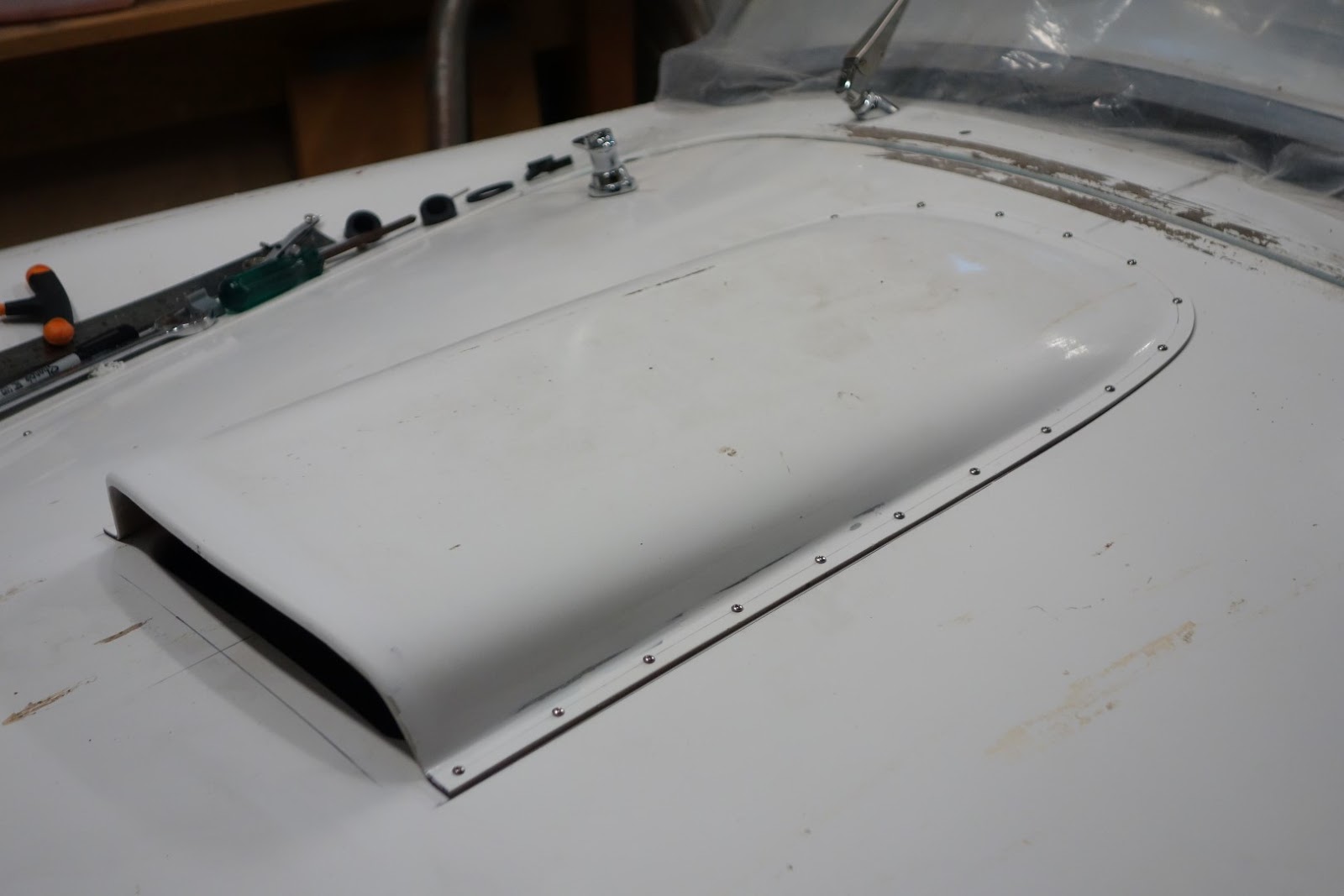
Next, mounted the Boot Lid on its hinges and put on the car to line up gaps, the left side gaps need opening up a few millimeters to get the handle and latch central.
There is a cross brace from side to side of the wheel arches which have the boot hinge mounts integrated. Everything lined up well with minimal adjustment. Machined up some spacers for the hinge joint so it locates same place each time its removed
Next was the mounting of the number plate lamp and plate mounting bracket.
The lamp came from Finishline Accessories, the Plate bracket was a local stainless part from Snakebite when they were in existence. It was sized perfect for the lamp, but didn't fit on the body well sitting 5mm higher than the boot lamp location. The bracket interfered with the lip below the lamp mount. After looking at how to modify the bracket neatly, I decided it was easier and neater to file off the lip on the boot for a much cleaner finish.
The task of hiding the number plate wire between the inner and outer lining and getting it to route from the hinge end to the number plate location was the challenge with a piece of bent brazing rod with a hook on the end of it, once I sited it at the hole, grabbed it with the pliers, hooked on the wires and dragged it back through the boot lid.
I'm using 10mm quick release Hitch Pins to mount the boot as well, same as the bonnet.
To remove, I still have to unbolt the gas strut, but wont need to wrench under the boot area.
As with the bonnet, I can remove and replace correctly very easily.

Once the boot sat aligned, mounted the boot lock handle and latch.
The latch pin was about 10mm too low to engage with the hook so made up a spacer to place under the latch pin bracket.

Last job was to mount the gas struts, 2x 315mm 200n Struts are provided by CR with mounting brackets for riveting or screwing to the boot floor, The struts locate to the hinges.
The struts take up usable space in the boot area, so I made a bracket that fits to the roll bar tube lower mount on the drives side and replace the two supplied 200n struts with one 400n strut. Finished with a much neater strut location and working perfectly with the boot lid becoming strut assisted from about 100mm of lift to fully opened.
I've decided not to line the entire boot area and have made a mat only for the floor, the boot walls look clean and came up well after coating with bed liner spray paint.
The floor also has 2x 80/20 low profile 1575 series extrusion mounted on it, this triangulates from the Tow Bracket location on the rear Chassis Cross Bar back to the original specified Roll Bar Hoop Third Leg mounting point on the chassis adding strength to the Tow point.
I can also locate a bracket on the 80/20 extrusion to mount a space saver spare wheel, or a long range aux fuel tank if i wish.

Last job in the boot area is to make the panel to close off the battery compartment area.

On the LH side at back is mounted a Bluetooth AM/FM Radio & Player, Also 2 spare power supply circuits,1x direct battery power & 1x IGN switch power if required.

On the RH side at back is a Projecta 1600mah battery trickle charge unit with 240v power tail for easy battery maintenance between use.


A cover panel will seal off the battery compartment.


Cleaned up all the seams, filled with fibre reinforced filler and sealed with Auto Body Sealer to keep any water out.

Sprayed the inside of the boot cavity with Bed Liner  paint.


The boot floor has holes in to fit over the rear bumper / quick jack mounts which are welded to the chassis members.


Covered the bumper mount holes with some aluminium sheet, cut to shape and then sealed around the mounting.


Everybody wants a piece of the action...
Made a template of the floor area from newspaper trimmed to shape, then cut from charcoal black marine carpet from Bunnings.


Radio mounted to the side of the boot compartment.


Battery charger hidden away behind the Roll Hoop Third Leg.
This pic also shows the single 400n gas strut and mounting to hold the boot lid open.


All done except for the Battery Compartment Cover.


Milling up the mould for the fibreglass Battery Compartment Cover.


A bit of filling and sanding before sealing and a couple of coats of mould release agent.


Filed the lip off the number plate lamp location on the boot lid so the lamp and bracket sat flush and aligned.

Exposed a large air bubble under the gelcoat surface in he process, will fill with fibre reinforced filler before body coating is done.


All fitted up and aligned, just needs to have the gaps filed up to size.


Friday, August 16, 2019

Sway Bar

A quick post, mounted the new Front Sway Bar, a redesigned upgraded part from CR to eliminate fowling the front wheel before full lock was reached.
After mounting I couldn't see what could stop the bar from drifting side ways in the mounts so i made up some small 2 piece collars, one for each side.


The collar clamps around the 22mm Sway Bar with some 4mm screws.

Tuesday, August 6, 2019

Wipers

Wipers are in.!
What an effort, hated this job and didn't go as expected.
Firstly, I've opted for a 2 wiper design based on the sweep and layout of the "Absolute Pace" Cobra.
The "CR"calls for a 3 wiper design to meet the design rules, but the "AP" design has been documented and passed engineering so I will use this as the basis for mine.
If it doesn't go through, then off comes the screen and on goes the race deflector screen, no windscreen means no wipers means no hassles.

My first issue was that I drilled one of the Wiper Box holes that poke through the body with insufficient angle and the Bezel then didn't fit correctly, I then had to file the holes to the correct angle but the Wiper Box was loose and didn't tighten up snugly, so ended up filling and reshaping the hole with fibre filler.

The next issue is that i had placed and made a bracket to hold the Wiper Motor on the firewall and now the Wiper Boxes didn't line up with the plane of the Wiper Motor.
The first Wiper box is only about 150mm from the Wiper Motor and needed a fair bend in the drive cable tube to meet up. After trying this, I found the cable was too tight in the tube to function smoothly, so made a new tube an fitted this to the unsecured Wiper Motor Then made a spacer block to pack out the Wiper Motor by another 16mm.
Its mounted up neat now and hidden behind the dash :)

Note for first timers,
Mount the Wiper Boxes first, then make the Drive Cable Tubes to fit, then fit the Wiper Motor, then make a Wiper Motor mounting bracket. :)


Not my best work.... but had fun milling up a spacer block.

The ECU is now mounted on the roof of the passenger foot well.

The front end is pretty much completed except for the washer bottle pump water line.


Monday, May 6, 2019

Bonnet Gaps, Rivets, and Scoop

After mounting the Bonnet Locks, I made up a little gauge block to mark out an even gap of 3.5mm around the Bonnet edge.
The opening in the body is very well formed and finished, the Bonnet however is over size from the laminating of the inner and outer skins and needs a bit of clean up.

I used dimensions from various documented cobra examples for the bonnet and scoop Rivet patterns and decided on 23 scoop rivets and 29 bonnet rivet patterns.

Finding the centre of the car to align the scoop was difficult with the LH & RH sides of the centre line not being identical at various points along the body.
This made the scoop look slightly tilted and off centre.
The scoop also isn't a symmetrical product either and it took me a while to realize that the slight radius in the scoop nose was the main culprit making one side slightly longer on the right hand side by 3mm, not much but enough to make a visual impact when looking straight on.

The air inlet opening in the bonnet is also about 5mm out of square to the bonnet line at the front further impacting the scoop opening look making it "wink" slightly on the LH Side.
This was also sanded back and shaped using a flapper wheel.


The scoop has the forward outrigger on each side.
To get the scoop nose radius correct, the little out riggers had to go.


After removing the out riggers, I created an even radius on the top of the scoop nose and sanded back the sides to make even.


Lots of finessing, and the scoop finally looks right.


A little more to come off the thickness of the scoop but its getting there.


This is the rivet pattern I used as a rough guide for the main dimensions, found this initially on the289register.com site and also club cobra and some builder blogs.


Scoop Rivet pattern is 11-1-11 (23)
Bonnet Rivet Pattern is 14-1-14 (29)


Wednesday, April 24, 2019

Bonnet Locks

Had the Bonnet and Boot Latch kit sitting patiently for many years,
I bought from Classic Revival at a time when Ian was intending to sell up his business.
The boot latch has a custom bracket which I thought at the time might be prudent to buy given the business may not have continued. Fortunately it ended in the capable hands of Daniel Steer, a previous employee of Ian Denner's and respected car restorer and fabricated in his own right.


This is one of the pair of Bonnet Handle and Latch Cams.
Its the oval base type, since purchasing these, I have also seen round base options.

The kit comes complete with Cams, Gaskets, and Stainless screws, which i replaced with Stainless 4mm Button Head Cap Screws.


This is the landing  on the body shell that the Bonnet Lock Cam protrudes through.
The Cam is off centre to the shaft so as the handle shaft turns to lock position, the Cam goes under the edge of the hole to lock the bonnet in position.
First step was to centre a hole in the landing and project some centre lines out to the body for transferring on to the closed bonnet. This will give me the overlapping hole centre line through the bonnet and landing


You can see in this pic that the Handle Shaft and Cam are on angle to the relatively level Landing on the Body and  the Bonnet Inner Panel.
This angle offsets the hole in the bonnet by 5mm to the centre of the Cam or 16.5mm to the centre of the Landing Hole.


Based on the 5mm offset, a new hole centre was marked and through drilled with 19mm hole saw parallel to the bonnet curvature.


Drilled an undersized 52mm hole for hole saw in the landing big enough for the Cam to go through but not quite final size in case a bit of finessing was required.

Note'
While the hole is centred in the landing, the shaft for the Handle is offset 11.5mm. towards the inside of the car


Under side of the Bonnet with Latch Holes.


Mounted the Handle.


Bonnet underside.
In this pic you can see an afterthought.
Nothing stops the handle from rotating through 360 degrees other than friction of the Cam against the body when locking, so i designed and printed an ABS plastic base plate for the underside of the handle mount that has a 3/4 boss on it and a Key that fits around the shaft and in between the boss walls to allow only a quarter turn.
Lock - UnLock.


You can see the Base and the Key in this pic along with aluminium flange and dress ring to go through the Landing and finish off the hole and protect the final paint.


Flange and dress ring installed.
After checking the Cam alignment through the hole, I used a flap sander on the drill to bring the hole diameter out to 55mm for the flange to fit through.


From the underside, you can see the angle the shaft and Cam enter the Landing hole.

This pic is the unlocked position.


In this pic, the Cam has rotated to the Locked position with the angled Cam face up against the bottom of the hole flange.


Friday, April 12, 2019

Dash Brace and Brake Bias Adjuster Mounting

After mounting the dash in for gauge location layout, I found the aluminium panel unsupported at the bottom and more flexible than I liked, so I've made up a brace that looks like the original tube brace from behind the dash to the tunnel.

On this tube brace, I've welded a bracket that the dash return lip on the bottom screws to that now stiffens it up and stops any flexing and vibration.

I also made up and welded another bracket to the tube brace for mounting 2 USB ports, 1 for the ECU and the other for Power or Media back to the radio in the boot area and a position for the Remote Brake Bias Adjuster.


Top of the Brace mounts to the dash bow.


The bottom of the tubes have 8mm studs that protrude through the tunnel and fixed from the underside.


Brace installed with Brake Bias Adjuster Knob and USB port mounted after a sandblast and Black Powder Coat by Best Coatings in Dandenong South.